GARTHWILSON wrote:
Welcome!
Most people here would leave BE tied high; but ruling out any use of NMI and IRQ would put a rather severe limit on what you can do with the computer. If you do ever plan to use them, tying them together would
not be a good thing either. If you give each one its own pull-up resistor, at least you leave the option of using the inputs later. My interrupts primer is at
http://6502.org/tutorials/interrupts.html . The interrupt-connections page of my 6502 primer is at
http://wilsonminesco.com/6502primer/IRQconx.html .
If board space on the free version of Eagle is that much of a problem, you could put the pull-up resistors on the back of the board, opposite an IC. Actually this board uses interrupts:
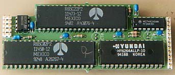
(It has the ROM on the back of the board.) This board is shown near the bottom of the
page on address decoding. Address decoding can be done much more simply than beginners tend to do, and you might save some parts (and room) there. The schematic of this board is very similar to the first schematic on the
circuit potpourri page.
Thanks for the reply! Also, your 6502 primer has been great help thus far!
My project is an extension of the Atari 2600 video game system. If you can believe it, the original design uses a 6507 which does not have any interrupt pins other then reset! I agree, it may be silly to rule out the possibility that I would like to use the interrupts in the future. I am literally almost out of space though, and a few resistors may put me over the limit. It is just good to know that if I really need to, I could tie them to 5v.
In case anyone is interested in my project, here's some info. Originally, I just wanted to replace the 6507 with a full 6502 for the extra address space (64K over 8K). In doing some research, I came across the WDC 65C02 and couldn't resist trying to overclock the processor. The Atari 2600 has a very primitive video chip with no video RAM whatsoever. There are just a few registers for colors and sprites that need to be changed on the fly as the electron beam of a television draws each pixel. In other words, about 70% of all the CPU time is spent drawing the screen with very precisely timed code. Overclocking the CPU can mean a tremendous improvement in the graphics you can pull off (and also incompatibility with all existing software

). I've also expanded the original 128 bytes or RAM to 16 KB. Here's a thread about the project:
http://atariage.com/forums/topic/201304 ... -wdc65c02/


