Joined: Fri Aug 30, 2002 1:09 am
Posts: 8423
Location: Southern California
|
A data link between two computers can be made through three wires plus ground, using their 6522 shift registers. I call the following method "SS22" from "synchronous serial link with 6522's," and although Samuel Falvo and I have talked about it by email and I've referred to it here in the past, did not realize there is virtually no public info on it.
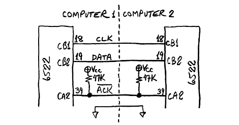
The 6522 VIA's serial port has many functions, some of which are brought out in the Tip of the Day topic (which I keep improving). If the 6522 had no bugs (I'll tell about the bug in a minute, with a work-around), two computers could pass data back and forth in half duplex this way:
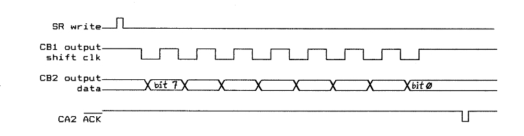
The signal order goes like this (bug or no bug), msb first:
If you need data to go in both directions, the data direction can be negociated in software, even if neither end is a master. That will not be covered here. The pull-up resistors on the CA2 line make sure a WDC 65c22 whose inputs are CMOS will float up to the high state anytime there is no driver, including when the port is not connected. Earlier ones like Rockwell and CMD had LS-TTL-type I/O, whose inputs basically pull themselves high in the absence of a driver.
For the sending computer, clock and data are outputs, and the acknowledge line is an input. For the receiving computer, it's the oposite.
Some 6522 abbreviations used here:
Code: SR shift register
T2 timer 2
PCR peripheral control register
ACR auxiliary control register
IFR interrupt flag register
IER interrupt-enable register
After the sending computer's 6522's SR is written by software (indicated by the top line in the diagram above), its clock line falls and the first data bit (msb of the byte) is put on the data line, in plenty of time to be valid and stable before the clock's rising edge which is what the receiving computer uses to clock the bit in. After the 8th bit (the lsb), the receiving computer's 6522's SR bit in the IFR will be set, and, if SR interrupts are enabled in the IER, the IRQ\ line will be pulled down. Whether using actual interrupts or not, the receiving computer can take as long as it wants to get around to reading the new byte shifted in, then it puts a low pulse on the CA2 line to tell the sending computer that it got it and that the sender can send another byte. There's no danger of overrun. The pulse does not need to be any particular length, because the CA2 pin of the sending computer will be set up to be an edge-triggered input that sets the CA2-active-edge flag in its IFR. Whether or not the corresponding flag in the IER is set to generate actual interrupts is again optional. The CA2 mode is set in the PCR, bits 3, 2, and 1.
For output, use SR mode 101, shift out under control of T2. For input, use SR mode 011, shift in under control of external CB1 clock. The SR mode is set in the ACR, bits 4, 3, and 2.
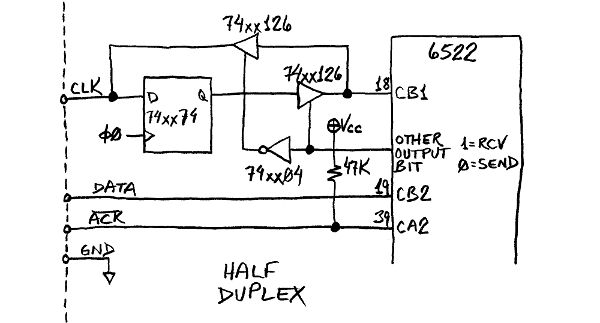
Now about the bug that threw a "wrench in the monkeyworks": All 6522's (including WDC's) have a bug in mode 011, in that if the externally supplied shift clock edge on CB1 falls within a few nanoseconds of the falling edge of phase 2, the CB1 edge will be ignored, so you lose a bit. Worse, you'll get framing errors on subsequent data (although they won't get reported). To get around it, put the external clock signal into the D input of a 74HC74 flip-flop, run the flip-flop's Q output to the 6522's CB1 pin, and clock the flip-flop with φ0 or φ2. The following works for unidirectional data:
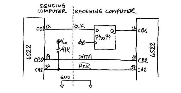
Unfortunately that's only good for one direction. Manually switching would take a circuit like this:
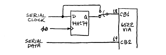
Switch is up for output, down for input.
Switching electronically would take something like the 74xx126 tristate quad buffer, controlled by another I/O bit:
Forehead slapper: Could I have been using shift out under external clock all this time (the last 15 years)? That should get away from the bug, as well as the extra logic and output bit it takes to get around it. The sender could put the low pulse on the CA2 line to tell the receiver that there's new data to shift out (instead of the receiver telling the sender that it's ready for the next byte now), and then the receiver can shift it in at its leisure. The sender will know when the shifting is finished. (Trying to explain something to someone else always helps figure things out better and make one aware of other possibilities or potential problems!) I have too many projects lined up to pursue it right now, so maybe someone else will beat me to it. Edit, years later: Synertek's AN-5 ap. note says the bug is in mode 111 (shift out under external shift clock) as well; so my proposed solution here, ie, using mode 111, would not work.
Bit rates: If the SR is producing the shift clock, T2-controlled, its maximum sending bit rate is Ф2/4. Assuming the clocks of the two computers are not synchronized, the receiving SR's maximum rate will be a little less than its Ф2/4, assuming the shift clock is produced by the sender. The slowest bit rate, T2-controlled, is Ф2/514, ie, Ф2/(2(n+2), where n is the low byte of the T2 counter and can start as high as 255. T2's counter high byte is ignored for this mode.
Since it is synchronous serial, the shift clock frequency does not matter as long as it is not too fast for the receiving end to operate. The default initial speed should be low enough that any anticipated computer could handle it, even at under 1MHz. I designed a commercial product in the 1980's with a 65c02 that usually ran at 100kHz to save battery power (the entire computer only took a mA or two) but it would kick its clock rate up to around 1MHz when it needed to get more done in a limited amount of time. The maximum rate for a computer running a little under 1MHz would be 150-200kbps, which, if you didn't have to stop between bytes for handshaking, would be about 20,000 bytes per second, a byte every ten instructions or so. That's still about four times as fast as the final 56K modems we all had before DSL took over. If the 65c22 were ever to reach 50MHz, SS22 could not go less than 97kbs on it, so 100kbps or so initial speed might be a good starting point. The slowest computer could go about 600kHz. If the two computers want to negociate something faster after they introduce themselves, go for it.
Now for a connector: Really only four connections are needed, meaning even a four-conductor RJ-11 telephone cord would work, and there are pre-made ones available at Radio Shack in different lengths. But for longish connections there should be ground wires between signal lines, or twisted with them. That means an RJ-45. Unfortunately neither of these fits into the .100" grid of holes in standard perfboard. Surprisingly, a plain 2x5 (10-pin) pin header takes less board space, and fits into the holes in the perfboard just fine. 10-pin is the smallest size I've seen the mating IDCs (insulation-displacement connectors, for pressing onto ribbon cable), so that's what I went with. It leaves enough to carry power also.
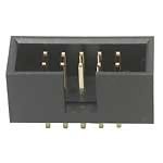
Here's a shrouded and keyed 10-pin header (WW ones are available too, but a bit hard to find):
and a 10-pin IDC that has not yet been pressed onto a ribbon cable:
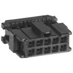
These are both keyed, which is not mandatory but is good to prevent plugging in backwards. Ejector hooks (which the above header does not have) are good also to help keep from bending pins when you remove the plug from the header.
Pinout: Here's what I've been using:
Code: +----+----+
(outside conductor of ribbon) ground | 1 | 2 | +12V (optional)
+----+----+
ground | 3 | 4 | clock (CB1)
+----+----+
ground | 5 | 6 | data (CB2)
+----+----+
ground | 7 | 8 | ACK\ (CA2)
+----+----+
ground | 9 | 10 | -12V (optional)
+----+----+
The ±12V on mine are only fed to one computer, and the other is powered through the SS22 ribbon cable. The actual voltage is seldom critical, and in my case it's usually more like ±9V, but I need the higher voltages to power the D/A converters and op amps, and my line drivers which take less board space than something like that well known MAX232 because they don't require the external capacitors for the voltage multiplier or the extra pins to connect to them. The +12V is also used for the amplifier for the monitor speaker. If you start with at least +7.5V, +5V is super easy to get with a 7805 regulator; but if you only have +5 and want a higher voltage for something, it's not so easy. I turn the high voltage up to +13 when I program PIC microcontrollers with the workbench computer.
Computers that never get their power from the SS22 ribbon cable should have diodes in series to avoid connecting two power supply outputs together. If it is unknown which way the power will flow in future set-ups, you might want to use switches or jumpers in place of diodes.
Since it's merely CB1, CB2, and CA2, the connector can also be used for other purposes besides an RS-232 replacement, like a chain of 4094, 4021, 74HC165, or 74HC595 shift registers for hundreds of input or output bits, or 9-level D/A, or bit inputs & outputs, etc..
I stumbled on a difference between the CMD and the Rockwell 65c22's. The first time, I used CMD's. When I replaced it with a Rockwell, the program no longer worked. It wouldn't get started with the first byte. The reason was that I was checking IFR<2> to see if the SR was ready for another byte. With CMD, this bit means "SR empty", whereas with the Rockwell, it means "8 shifts completed." These normally mean the same thing, but my program wouldn't start with the Rockwell part because even though the SR was ready, no shifts had occurred yet because I hadn't given it anything to transmit yet. I ended up using a RAM byte variable as a flag to tell the loop if the first byte had been sent yet.
In the first page of the topic on developing the 65SIB spec., we discussed using SS22 to make an HPIL-like interface. HP-IL stands for "Hewlett-Packard interface loop." There are a lot of nice things about HPIL. You can theoretically connect an almost unlimited number (over 900) of devices to one or more controllers with only two small connectors on each device or controller, one being "in" and the other "out". The "out" of each device goes to the "in" of the next, connecting everything in a big circle. Since each output goes to only one input (ie, that of the next device), there are no fan-out limitations like bussed connections have. No line needs to be bi-directional. The initial controller initiates auto addressing. Control can be passed from one controller to another. Every message goes around the loop in the same direction regardless of origin, and when it comes full circle, the originator of the message can check to make sure it did not get corrupted on its way around. In the auto addressing, the controller starts it and tells the first device, "You're #1," which passes the message and the next one which says, "Then that means I'm #2" and so on, until it gets all the way back around, and the controller knows how many there are. Each device knows its address, model number, device type, and capabilities, and the controller can poll these and act based upon them. I've used HP-IL extensively and can't say enough good about it; but the reason we didn't go with the idea for 65SIB though was that it requires every device to be intelligent, and every message has to go through every device, taking longer as each device looks to see if the message is addressed to it, and if not, passes it on without acting on it.
Necessity is the mother of invention, and the reason I originally started using this in 1997 was that I was feeding source code to the workbench computer (Bench-1) from the PC over RS-232 using the 65c51 ACIA, but I didn't have ACIAs any faster than 2MHz nor could I find any to buy at the time, and I wanted to bump the computer speed way up. I made a separate, more limited workbench computer, Bench-2, which runs at under 1MHz (RC-controlled, not crystal) to act as a buffer and I really have not used it for anything else. This one takes the RS-232 from the PC and sends the data to Bench-1 over the SS22 line. (Later I did find 4MHz 65c51's and put them in Bench-1, but have used them very little. Now WDC has them in 14MHz.) The SS22 takes away a lot less 6522 I/O pins than a parallel interface would, leaving more for projects.
_________________ http://WilsonMinesCo.com/ lots of 6502 resources
The "second front page" is http://wilsonminesco.com/links.html .
What's an additional VIA among friends, anyhow?
|
|


