6502.org Forum  Projects  Code  Documents  Tools  Forum
It is currently Sat May 04, 2024 11:06 pm

All times are UTC


Post new topic Reply to topic  [ 18 posts ]  Go to page 1, 2  Next
Author Message
 Post subject: My 6502 computer
PostPosted: Wed May 01, 2024 10:11 am 
Offline

Joined: Wed Apr 10, 2024 7:24 am
Posts: 11
I would like to build a 6502 based computer. I'm not very experienced so it wil be quite an ambitious project. I wanted to share my plans with you all so you have an idea about what it is I want to achieve. I have a lot of loose ends that I need to solve I will need to make a lot of choices but I have a general idea. So here is my plan.

I want to build a computer that is a bit like the early home computers from the 70's and early 80's. I want it to be in a 3D printed case with a build in parallel ascii keyboard. I want it to have two controller/joystick ports (Sub-D 9). I want to be able to control the computer via a terminal from a modern laptop. And I want it to have some kind of storage to store programs. And it also should have color video output of some kind. And also I want it to have an audio output. I want to use this computer for game development as well as os development so that is why I want to have video/audio output. I'm from 1980 so I'm a bit spoiled I just like color better than only grayscale.

Now I already did a lot of research but there are many options so here are some options I consider and ideas of what I want to achieve.

Clock

I want to use a 10.738635MHz clock that I want to divide by 3 as a system clock. I need the 10.738635MHz clock for my video chip which I will discus later. By diving it by 3 it can also be used for the sound chip I would like to use. This way I would have a 3.579545MHz system clock.

The memory map

I want to build something similar as Dirk Grappendorf did with his 6502 home computer https://www.grappendorf.net/projects/6502-home-computer/#table-of-contents. I have a 28c256 ROM chip and 62256 SRAM chip that I want to use. I want to use the same memory map:

$0000 - $00FF RAM - Zero page
$0100 - $01FF RAM - Stack
$0200 - $7EFF RAM
$7F00 - $7F1F VIA 1
$7F20 - $7F1F VIA 1
$7F40 - $7F5F ACIA
$7F60 - $7F7F Video
$8000 - $FFFF ROM

But I want to add a second 65C22 and a 65C51 chip. Here is a screenshot simulation made in Digital:

Attachment:
File comment: Address decoding
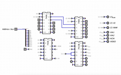
Scherm­afbeelding 2024-05-01 om 10.31.11.png
Scherm­afbeelding 2024-05-01 om 10.31.11.png [ 369.01 KiB | Viewed 206 times ]


The parallel ASCII keyboard

I want to build the keyboard from logic chips and Cherry MX style switches. The idea is to create a keyboard that outputs 7-bit ASCII codes that I want to connect up to a 6522 via. I have found an old schematic in an old Brochure of the Cherry B70 Pro keyboard on bitsavers http://bitsavers.trailing-edge.com/components/cherry/keyboards/B70-05AB_Pro_Keyboard/PRO-977-2_B70-05AB_Pro_Keyboard_Brochure.pdf. This keyboard is quite complex and it has a lot of optional parts that I'm not interested in. I want to try to create something similar but a lot simpler. I like the combination of the 4-bit counters and the 74150 (16-line to 1-line data selector/multiplexer) and 74154 (4-to-16 line decoder/demultiplexer, inverting outputs) to scan a keyboard matrix. But the logic for the shift/Caps Lock (Alpha Lock in the schematic) is quite complex and I don't really understand what is going on. I did an attempt to replicate the circuit in Digital here is the result:

Attachment:
File comment: Attempt to replicate the Cherry B70 Pro keyboard logic
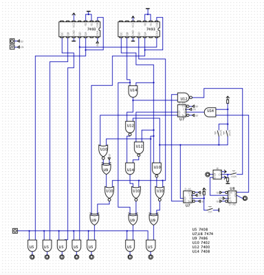
Scherm­afbeelding 2024-05-01 om 11.24.05.png
Scherm­afbeelding 2024-05-01 om 11.24.05.png [ 485.77 KiB | Viewed 206 times ]


But unfortunately it does not work. I added an extra flip-flop to for keeping the caps lock on after clicking the key once and turn it of when clicking a second time. Unfortunately Cherry does not make alternate action switches any more since 2015 https://deskthority.net/wiki/Cherry_MX_Lock.

As I could not figure out how the logic of the Cherry B70 Pro works I tried to get something working myself. The theory is quite simple. I found the article Things Every Hacker Once Knew http://www.catb.org/esr/faqs/things-every-hacker-once-knew/#_ascii there is a explanation about the workings of ASCII together with the Wikipedia page about the Control key https://en.wikipedia.org/wiki/Control_key I found out how this could work. The Caps lock/Shift key toggles bit 32 or bit 16 dependent on the key you clicked (for 0-9 and keys : ; < = > ? bit 16 is toggled and for keys a-z and ` { | } ~ DEL bit 32 is toggled). The control key could be implemented by doing a bitwise AND on the key value with 0x1F.

I have a working simulation made in Digital but it doesn't take bit-5 into account yet and the clock circuit is not there yet I wanted to keep it as simple as possible and just focus on the shift/caps lock and control logic. Here is an screenshot taken from the simulation. It has tests and they all pass but the implementation is not correct. Perhaps someone has some tips or suggestions.

Attachment:
File comment: Image of the simulation in Digital
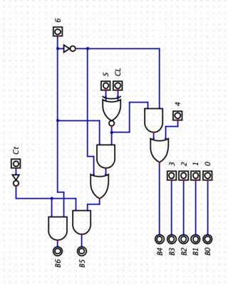
Scherm­afbeelding 2024-05-01 om 10.04.45.png
Scherm­afbeelding 2024-05-01 om 10.04.45.png [ 148.71 KiB | Viewed 206 times ]


The keyboard will be on a separate PCB.

Serial connection

I'm not really sure how to get this to work as I did not researched this part but I guess it can be done the way Ben Eater did or perhaps I could use another option and use something like what was done in the W65C02SXB SBC hook up a 65C22 via up to a FT245RL and have a USB connection. But the FT245RL is a SMD chip and I'm not sure if I'm able to solder these I guess my soldering iron is not suitable for the job. I once did an attempt and failed badly. Perhaps it will be much more doable if I use a hot air gun for soldering SMD components?

Controller/joystick ports

This should be doable by connection the ports up to one of the 65C22 VIA chips. I'm not sure how to do this the proper way I guess I need to add some multiplexing. Can I use the same port of the 65C22 for both the controllers and the keyboard? I also found a sound chip and perhaps some storage device which I want to hook up to a VIA so I might need the other port for that or use the second VIA.

Audio/Video

I have a SN76489 chip for audio. I think I need to hook this up to the 65C22 to make this work. It also needs a clock

I want to use the TMS9918 chip for video output there are some schematics that can be found that use SRAM for this chip so I just can use that.

These two chips can still be found easily now, but I don't know if that will always be the case. These are old chips that are no longer made the same applies to the SN76489.
I'm a bit worried that I wont be able to replace them if one of them breaks. So I'm not really sure if I would use these chips or just use something like a Pi Pico to emulate them.
I can also get a VGA output with the Pi Pico. When I decide to use the Pi Pico I can use another clock as well. I now plan to use a 10.738635MHz clock because it is needed for the TMS9918 and when dividing it by 3 I can use it for the SN76489 and as a system clock of 3.579545MHz.

I think it is a good idea make a separate PCB for the audio and video so I will be able to replace it. This way I can also try out multiple options.

Storage

Keeping it in memory and losing it when turning off the machine is a shame. So I also want to be able to store programs I write on the machine somewhere.
I don't like the idea to buy and old tape drive of floppy drive to store data so I'm looking for a more modern solution. I'm thinking about using a SD-card reader or using a compact disk but I havent decided yet. I have an old 32mb compact and a compact disk to IDE adapter that I could use. But I also have a SD-card reader breakout board.

Pfiew this was a lot of writing!

If anyone has tips, suggestions or comments I really like to hear what you all think.

Thanks!


Top
 Profile  
Reply with quote  
 Post subject: Re: My 6502 computer
PostPosted: Wed May 01, 2024 11:59 am 
Offline

Joined: Mon Jan 19, 2004 12:49 pm
Posts: 677
Location: Potsdam, DE
I'm currently designing (yet another) SBC using a 65c02. At present:
48k RAM,
~16k EEPROM/FLASH,
250 bytes of IO space at 0xff00,
640x400 (as 80x25 chars) VGA output (might turn out to be 640x480)
Serial I/O using SC16IS741A
RTC using MCP795
Compact Flash for storage, 8-bit mode.

There are two SPI chips on board which will use an addressable buffer (in and out) for data management. For the serial link I will use an FTI232 USB-SIL cable which will plug straight onto a pin header.

With the exception of the processor, it will all be SOIC or TSSOP surface mount; with a ZIP socket for the prom.

I'm still contemplating whether to include a keyboard onboard. Cherry switches have been historically lovely, but a cherry keyboard is not inexpensive (and if you brew your own you'll need to make the case and organise key-caps as well. I'm most likely to get a cheapo PS/2 keyboard and bit-bang it...

Soldering irons, temperature controlled, are not expensive compared to the risk of zapping a board-full of components. But hot air guns are cheaper still, and along with solder paste syringes, even without a stencil, provide a very easy way to mount SOIC and smaller parts (though SOIC is well within the ability of anyone who can do a clean solder join using an iron and a light hand :D )

I don't like to use any chip which is not currently available new; that's just me.

(And check out Garth's pages!)

Neil


Top
 Profile  
Reply with quote  
 Post subject: Re: My 6502 computer
PostPosted: Wed May 01, 2024 12:17 pm 
Offline

Joined: Wed Apr 10, 2024 7:24 am
Posts: 11
barnacle wrote:
I'm currently designing (yet another) SBC using a 65c02. At present:
48k RAM,
~16k EEPROM/FLASH,
250 bytes of IO space at 0xff00,
640x400 (as 80x25 chars) VGA output (might turn out to be 640x480)
Serial I/O using SC16IS741A
RTC using MCP795
Compact Flash for storage, 8-bit mode.

There are two SPI chips on board which will use an addressable buffer (in and out) for data management. For the serial link I will use an FTI232 USB-SIL cable which will plug straight onto a pin header.

With the exception of the processor, it will all be SOIC or TSSOP surface mount; with a ZIP socket for the prom.

I'm still contemplating whether to include a keyboard onboard. Cherry switches have been historically lovely, but a cherry keyboard is not inexpensive (and if you brew your own you'll need to make the case and organise key-caps as well. I'm most likely to get a cheapo PS/2 keyboard and bit-bang it...

Soldering irons, temperature controlled, are not expensive compared to the risk of zapping a board-full of components. But hot air guns are cheaper still, and along with solder paste syringes, even without a stencil, provide a very easy way to mount SOIC and smaller parts (though SOIC is well within the ability of anyone who can do a clean solder join using an iron and a light hand :D )

I don't like to use any chip which is not currently available new; that's just me.

(And check out Garth's pages!)

Neil


Thanks Neil. How did you create your VGA output?

I'm already reading a lot on Garth's pages. I do not have a completed schematic yet but I already used one of his reset circuits for my computer.

I'm also a bit worried to use chips that are not currently available. But if I create a separate pcb for those old chips I will be able to replace it with another circuit that has currently available chips. With a good connector between the boards that would be possible.


Top
 Profile  
Reply with quote  
 Post subject: Re: My 6502 computer
PostPosted: Wed May 01, 2024 1:12 pm 
Offline

Joined: Mon Jan 19, 2004 12:49 pm
Posts: 677
Location: Potsdam, DE
A couple of choices: either a prom-based state machine, a discrete counter approach, or using a second 6502 as a video address generator. The discrete counter has been at least partially tested, and there's nothing tricky in it so no reason to worry that it wouldn't work...

viewtopic.php?f=4&t=7979
viewtopic.php?f=4&t=7832

and others from other users here.

Neil


Top
 Profile  
Reply with quote  
 Post subject: Re: My 6502 computer
PostPosted: Thu May 02, 2024 7:11 am 
Offline

Joined: Wed Apr 10, 2024 7:24 am
Posts: 11
I was following Ben Eaters video's on his worst video card https://eater.net/vga. It is quite interesting but the end result is not what I have in mind. Later I also found the video series of George Foot https://www.youtube.com/watch?v=EC1Ous1zT5w&list=PLWKtKD_FaUF6IsFc1maERpOwWM2hrOM3b where he is improving Ben Eaters video card. I like the end result he posted the schematics on Github https://github.com/gfoot/simplevga6502.

But I'm not sure if I want to make my project more complex as it is already quite a challenge already. But perhaps I can do that later because like I said I want my video output on a separate pcb so I will be able to add multiple options.

Here is a block diagram of what I would like to create:

Code:
+---------------------+
|  ASCII Keyboard pcb |
+---------------------+
          |
          v
+---------------------+
|    Computer pcb   |
|    6502 CPU         |
|    6522 IO * 2      |
|    6551 serial IO   |
|    RAM/ROM          |
|    2xD-sub 9        |
+---------------------+
          |  ^     
          v  |     
+---------------------+
|    Video/Audio pcb  |
+---------------------+


Top
 Profile  
Reply with quote  
 Post subject: Re: My 6502 computer
PostPosted: Thu May 02, 2024 7:51 am 
Offline

Joined: Wed Apr 10, 2024 7:24 am
Posts: 11
barnacle wrote:
I'm still contemplating whether to include a keyboard onboard. Cherry switches have been historically lovely, but a cherry keyboard is not inexpensive (and if you brew your own you'll need to make the case and organise key-caps as well. I'm most likely to get a cheapo PS/2 keyboard and bit-bang it...
Neil


I know it will be easier and cheaper to use a PS/2 keyboard but I really want to pull this of and create a real parallel ASCII keyboard. The Cherry switches are expensive so I bought cheaper Cherry MX compatible Gateron Pro switches and I also already bought a keycap set. I need to design the pcb and order the pcb somewhere and the components and solder it. I also have another option for this pcb and have a much simpler matrix with just one 4-bit counter and the 75154:

Attachment:
Scherm­afbeelding 2024-05-02 om 09.29.25.png
Scherm­afbeelding 2024-05-02 om 09.29.25.png [ 710.08 KiB | Viewed 126 times ]


This also outputs a 8-bit value. The only problem is it does not handle shift/caps lock and control. I could add a eeprom to decode the 8-bit value and the shift/caps lock or control keys. The 8-bit value is not ASCII here bit just the value of the counter and the row information.

This design was my first attempt to create a keyboard design it is much simpler. I just has straight rows and columns.
But I find it much more satisfying and educational to design a solution that outputs ASCII codes from logic chips. I don't have a complete working solution yet but I hope I can figure it out.


Top
 Profile  
Reply with quote  
 Post subject: Re: My 6502 computer
PostPosted: Thu May 02, 2024 8:47 am 
Offline

Joined: Mon Jan 19, 2004 12:49 pm
Posts: 677
Location: Potsdam, DE
Well, you _could_ e.g. use a 6502 and 6522 combination to drive the rows and read the columns (or even just driver/buffer chips) and let the 6502 handle generating the ASCII output - plus n-key rollover, control, alt, and shift/shift-lock, and throwing an interrupt at the main processor when a new key is available. Or arrange that the output is delivered serially. Or even, do as it was done of old and have the main processor scan the keyboard directly, every now and then.

For a single chip solution, any number of ARM/AVR/PIC/8051 options present themselves. Discrete logic to scan the keyboard is easy. Managing the scanned output is a bit more complex. Though I see exactly where you're coming from!

Neil (off to look for PS/2 specs... to be honest, the only thing really stopping me having a go myself is not finding any keys and caps at sane prices.)


Top
 Profile  
Reply with quote  
 Post subject: Re: My 6502 computer
PostPosted: Thu May 02, 2024 9:26 am 
Offline

Joined: Wed Apr 10, 2024 7:24 am
Posts: 11
barnacle wrote:
Well, you _could_ e.g. use a 6502 and 6522 combination to drive the rows and read the columns (or even just driver/buffer chips) and let the 6502 handle generating the ASCII output - plus n-key rollover, control, alt, and shift/shift-lock, and throwing an interrupt at the main processor when a new key is available. Or arrange that the output is delivered serially. Or even, do as it was done of old and have the main processor scan the keyboard directly, every now and then.


Yes you are right. This is how it was done in 6502 based computers like the Commodore 64, BBC Micro etc. It is an option.

barnacle wrote:
For a single chip solution, any number of ARM/AVR/PIC/8051 options present themselves. Discrete logic to scan the keyboard is easy. Managing the scanned output is a bit more complex. Though I see exactly where you're coming from!


Using a microcontroller is also an option this was also done in older computers. I found this article about matrix scan encoding https://telcontar.net/KBK/tech/matrix_scan. That is where I also found the information about the Cherry Pro as well.

I also found keyboards with a ROM chip as a lookup table. Don Lancaster's TV Typewriter also uses a ROM chip the 2513 character generator https://amigan.yatho.com/2513.pdf. So my first attempt could also still be an option.

I still think it would be more rewarding for me at least to have an ASCII keyboard made of logic chips. I first thought about using a modern keyboard layout but that would be a pain as the layout has some differences.


Top
 Profile  
Reply with quote  
 Post subject: Re: My 6502 computer
PostPosted: Thu May 02, 2024 11:30 am 
Offline

Joined: Mon Jan 19, 2004 12:49 pm
Posts: 677
Location: Potsdam, DE
I note that this https://www.digikey.de/en/products/deta ... 4JYgC6AvkA is still available, if you happen to want twenty :mrgreen:

Neil


Top
 Profile  
Reply with quote  
 Post subject: Re: My 6502 computer
PostPosted: Thu May 02, 2024 12:04 pm 
Offline

Joined: Wed Apr 10, 2024 7:24 am
Posts: 11
barnacle wrote:
I note that this https://www.digikey.de/en/products/deta ... 4JYgC6AvkA is still available, if you happen to want twenty :mrgreen:

Neil


Lol no thanks.

I could just program an eeprom to do something like that. In my simple keyboard something like that would be possible.
There the 4-bit counter indicates the column selected. I have 4 rows in my design. When you press a switch and the column is active it would output the clock in the first 4 bits of the 74245 and then the column number in the following 3 bits. In this example column number 1 (counting from zero) and row 2 are selected:

Attachment:
Scherm­afbeelding 2024-05-02 om 13.53.08.png
Scherm­afbeelding 2024-05-02 om 13.53.08.png [ 705.79 KiB | Viewed 98 times ]


I could hook the output of the 74245 up to an eeprom together with the shift/caps-lock and control keys to the address pins of the eeprom and have the eeprom programmed with the right ASCII code at that address. The 74148 and the logic gates there are to encode the selected row.

In my design I used only 7 out of 8 bits as output. I could add another row or column to make use of that last bit.


Top
 Profile  
Reply with quote  
 Post subject: Re: My 6502 computer
PostPosted: Thu May 02, 2024 2:59 pm 
Offline

Joined: Mon Sep 17, 2018 2:39 am
Posts: 133
Hi!

You could also use an Atari POKEY, so you have sound, serial port, paddles and keyboard :)

Or at least you could copy the way it was done there: http://krap.pl/mirrorz/atari/homepage.n ... %20circuit

It uses two 4051 chips, one for the rows and another for the columns, this allows scanning 64 keys with only 7 pins, plus another pin for the "special" keys, SHIFT, CONTROL and BREAK:

Attachment:
File comment: Keyboard scan circuit
pokey-key.png
pokey-key.png [ 7.53 KiB | Viewed 82 times ]


If you want to use an EPROM directly, you will need to deal with debouncing the keyboard and avoid getting multiple key presses generate an stream of codes - this happens a lot when you press one key with one hand and the next with the the other hand, you will generate both keys at the frequency of your scan.

IMHO, it is much easier to simply do the decoding in your 6502 code, after debouncing and detecting multiple key presses.

Have Fun!


Top
 Profile  
Reply with quote  
 Post subject: Re: My 6502 computer
PostPosted: Thu May 02, 2024 4:21 pm 
Offline
User avatar

Joined: Tue Feb 28, 2023 11:39 pm
Posts: 140
Location: Texas
viridi wrote:
Attachment:
The attachment Scherm­afbeelding 2024-05-02 om 13.53.08.png is no longer available


Lot of inverters there that appear to be changing the signal multiple times. Might be able to strip a few of those out.

I'm presuming the goal of the 245 is a connection to the 6502 databus. You'll likely want to drive that OE pin with the 6502 and not when someone presses a key. (Otherwise you'll be sending signals down the databus when other devices are trying to use it.)

I'd likely use that logic to toggle a flop to signal an interrupt on the 6502 that a key is ready to be read.

When I was looking into to doing this with a PIC, I planned to use some of the onboard memory of the PIC as a ring buffer for the keys pressed. That way the key strokes could be read by the 6502 when it was ready.

Something similar could be done in hardware, but I haven't been able to find any memory ICs with a reasonably small queue. (Most are phenomenally huge these days, at least for a simple keyboard buffer)

Edit:
Here's what I'm thinking with simplifying this:
Attachment:
Screenshot 2024-05-02 114810.png
Screenshot 2024-05-02 114810.png [ 62.96 KiB | Viewed 68 times ]


(Edit/Edit, fixed a minor logic flaw I saw)


Top
 Profile  
Reply with quote  
 Post subject: Re: My 6502 computer
PostPosted: Thu May 02, 2024 6:09 pm 
Offline
User avatar

Joined: Fri Aug 03, 2018 8:52 am
Posts: 746
Location: Germany
why not just use one of the VIAs directly?
assuming you don't use the VIA's handshaking feature you can use the CA/CB pins as free I/O.

so a 74HC163 with it's clock and reset inputs hooked up the VIA's CA2 and CB2 pins (with some pull ups or pull downs). the output of the counter goes to a 74HC154 which then goes to the keyboard matrix. the other side of the matrix is then simply hooked into the VIA's regular IO pins (however many are required, though even just 8 inputs give you 128 keys).

so to scan the keyboard (assuming 74HC163 clk = CA2, reset = CB2, matrix input on Port A) once you:
1. reset the counter by pulsing CB2
2. read the value from Port A and store it into memory
3. pulse CA2
4. repeat 2 and 3 a total of 16 times
5. now either leave the raw keyboard data in memory for non-ISR code to handle or directly convert it to a bit/bytemap of which keys are being pressed at the moment.

sure it's a lot more software overhead and based on polling (i recommend some form of timer interrupt anyways), but it keeps the IC count low and makes hardware less complex.
which is good because fixing software mistakes is a lot easier and requires fewer cuts and botch wires than fixing hardware mistakes!

plus you still have one of the ports free which you could use for some software SPI for some cheap expansion (SD Card, RTC, various sensors, tiny displays, etc).


Top
 Profile  
Reply with quote  
 Post subject: Re: My 6502 computer
PostPosted: Fri May 03, 2024 4:58 am 
Offline

Joined: Wed Apr 10, 2024 7:24 am
Posts: 11
dmsc wrote:
Hi!

You could also use an Atari POKEY, so you have sound, serial port, paddles and keyboard :)

Or at least you could copy the way it was done there: http://krap.pl/mirrorz/atari/homepage.n ... %20circuit

It uses two 4051 chips, one for the rows and another for the columns, this allows scanning 64 keys with only 7 pins, plus another pin for the "special" keys, SHIFT, CONTROL and BREAK:

Attachment:
pokey-key.png


Interesting but after a quick search this seems like an expensive solution.

dmsc wrote:
If you want to use an EPROM directly, you will need to deal with debouncing the keyboard and avoid getting multiple key presses generate an stream of codes - this happens a lot when you press one key with one hand and the next with the the other hand, you will generate both keys at the frequency of your scan.


I plan to add debouncing and anti-ghosting to the keyboard.

dmsc wrote:
IMHO, it is much easier to simply do the decoding in your 6502 code, after debouncing and detecting multiple key presses.


I know but I like the challenge.


Top
 Profile  
Reply with quote  
 Post subject: Re: My 6502 computer
PostPosted: Fri May 03, 2024 5:10 am 
Offline

Joined: Wed Apr 10, 2024 7:24 am
Posts: 11
Yuri wrote:
Lot of inverters there that appear to be changing the signal multiple times. Might be able to strip a few of those out.


You are right I just could not get it working without them. It needs some further investigation.

Yuri wrote:
I'm presuming the goal of the 245 is a connection to the 6502 databus. You'll likely want to drive that OE pin with the 6502 and not when someone presses a key. (Otherwise you'll be sending signals down the databus when other devices are trying to use it.)

I'd likely use that logic to toggle a flop to signal an interrupt on the 6502 that a key is ready to be read.


No I want to hook it up to one of the ports of a VIA. The VIA then can signal an interrupt to the 6502.

Yuri wrote:
Edit:
Here's what I'm thinking with simplifying this:
Attachment:
Screenshot 2024-05-02 114810.png


(Edit/Edit, fixed a minor logic flaw I saw)


Interesting I will have a look thanks.


Top
 Profile  
Reply with quote  
Display posts from previous:  Sort by  
Post new topic Reply to topic  [ 18 posts ]  Go to page 1, 2  Next

All times are UTC


Who is online

Users browsing this forum: No registered users and 8 guests


You cannot post new topics in this forum
You cannot reply to topics in this forum
You cannot edit your posts in this forum
You cannot delete your posts in this forum
You cannot post attachments in this forum

Search for:
Jump to: