6502.org Forum  Projects  Code  Documents  Tools  Forum
It is currently Sat May 04, 2024 3:03 am

All times are UTC


Post new topic Reply to topic  [ 11 posts ] 
Author Message
PostPosted: Fri May 03, 2019 4:48 am 
Offline

Joined: Sat May 26, 2018 1:00 am
Posts: 26
Location: Riverton, UT
I just wanted to share my little project and a small step stone to my ultimate goal of a 65816 based SBC.
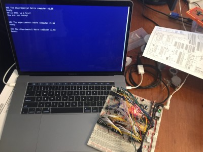
It started as this
Attachment:
IMG_1636.JPG
IMG_1636.JPG [ 282.44 KiB | Viewed 1172 times ]


A 65C02 at 1Mhz, a 65C51 for serial, a 65C22, two 32k RAMs, and a 128k Flash ROM on bread boards and an unmanageable mess of wires.
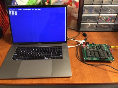
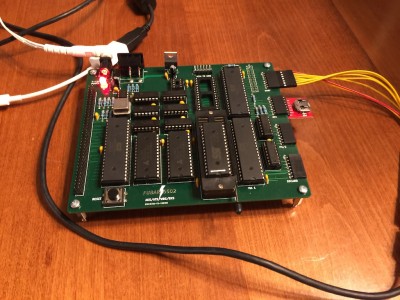
It became this
Attachment:
IMG_1643.JPG
IMG_1643.JPG [ 295.17 KiB | Viewed 1172 times ]
Attachment:
IMG_1644.JPG
IMG_1644.JPG [ 327.45 KiB | Viewed 1172 times ]


It is basically what I built on the breadboards with a second 65C22 dedicated to bit banging SPI. The design still accommodates the 65C51 which I used to boot strap my SPI code, but now that I have SPI working, I am using a MAX3100 SPI UART instead. I also have a SPI RTC connected, and I am currently working on connecting a PS/2 keyboard with an ATMega328 or 1284 handling the PS/2 protocol and communicating with the SBC through SPI.

And the best thing is I have it running rock solid at 8Mhz! My software SPI implementation seems to have no problem keeping up with a 115200 baud rate on the MAX3100.

Many thanks to Garth Wilson for making his SPI code available which is the basis for my SPI implementation. I added support for SPI mode 0-3 and full duplex communication. If anyone is interested, I will make my SPI implementation available on GitHub or something.

Thanks to everyone who has given me pointers and advice.


Top
 Profile  
Reply with quote  
PostPosted: Fri May 03, 2019 7:19 am 
Offline
User avatar

Joined: Thu Dec 11, 2008 1:28 pm
Posts: 10793
Location: England
Looks great - thanks for sharing! Do please put your code up on github (or similar)


Top
 Profile  
Reply with quote  
PostPosted: Fri May 03, 2019 10:25 am 
Offline
User avatar

Joined: Wed Feb 14, 2018 2:33 pm
Posts: 1401
Location: Scotland
Looks good! I do like the plug-in SPI things too.

Cheers,

-Gordon

_________________
--
Gordon Henderson.
See my Ruby 6502 and 65816 SBC projects here: https://projects.drogon.net/ruby/


Top
 Profile  
Reply with quote  
PostPosted: Sat May 04, 2019 6:10 am 
Offline

Joined: Tue Feb 24, 2015 11:07 pm
Posts: 81
Nice build! I especially like the R/A female headers for ports! What's with the resistor across the pins of the top 6522?


Top
 Profile  
Reply with quote  
PostPosted: Mon May 06, 2019 3:11 pm 
Offline
User avatar

Joined: Sun Jun 30, 2013 10:26 pm
Posts: 1927
Location: Sacramento, CA, USA
You should put some rubber feet on that beauty so it doesn't fubar your desktop even more than it already has.

_________________
Got a kilobyte lying fallow in your 65xx's memory map? Sprinkle some VTL02C on it and see how it grows on you!

Mike B. (about me) (learning how to github)


Top
 Profile  
Reply with quote  
PostPosted: Mon May 06, 2019 7:26 pm 
Offline

Joined: Sat May 26, 2018 1:00 am
Posts: 26
Location: Riverton, UT
unclouded wrote:
Nice build! I especially like the R/A female headers for ports! What's with the resistor across the pins of the top 6522?


The resistor across the 6522 is what happens when you accidentally buy a 65C22N when you meant to get a 65C22S. The 65C22N has a open drain IRQ and the 65C22S does not. The open drain version can have the IRQ line used in a wired OR and needs a pullup resistor. The board was designed for the 65C22S and didn't have the pullup. Bodge a 3K3 resistor from IRQ across to VCC and voila, a 65C22N sorta becomes a 65C22S!


Last edited by bradleystach on Mon May 06, 2019 7:31 pm, edited 1 time in total.

Top
 Profile  
Reply with quote  
PostPosted: Mon May 06, 2019 7:28 pm 
Offline

Joined: Sat May 26, 2018 1:00 am
Posts: 26
Location: Riverton, UT
barrym95838 wrote:
You should put some rubber feet on that beauty so it doesn't fubar your desktop even more than it already has.

By desk you must mean kitchen table :D
The wife is still grumpy about that haha.


Top
 Profile  
Reply with quote  
PostPosted: Mon May 06, 2019 10:07 pm 
Offline
User avatar

Joined: Fri Aug 30, 2002 1:09 am
Posts: 8430
Location: Southern California
bradleystach wrote:
Bodge a 3K3 resistor from IRQ across to VCC and voila, a 65C22N sorta becomes a 65C22S!

If you put more than one on the IRQ\ or NMI\ line, you'll want to have only one resistors on there, rather than loading the line more heavily with each additional VIA.

There are more differences between the N and S versions though. (I know you said "sorta.") From WDC's website:
Quote:
W65C22S/W65C22N Differences
  • The W65C22S is lower power, faster and direct drive outputs with no current-limiting resistors on outputs ports.
  • The W65C22N is plug-in replacement of NMOS 6522 devices with current-limiting resistors on output ports.
  • The W65C22N does not have bus-holding devices on the input IO pins.
  • The W65C22N IRQB is an open-drain output that CAN be Wire-ORd, unlike the totem-pole output of the W65C22S (some customers have had to use a diode in series with the IRQB output when using the W65C22S in their systems that had wire-ORd interrupts).

_________________
http://WilsonMinesCo.com/ lots of 6502 resources
The "second front page" is http://wilsonminesco.com/links.html .
What's an additional VIA among friends, anyhow?


Top
 Profile  
Reply with quote  
PostPosted: Mon May 06, 2019 10:56 pm 
Offline

Joined: Sat May 26, 2018 1:00 am
Posts: 26
Location: Riverton, UT
Yes, there are more differences than just the open drain IRQ, but that was the difference that got me.
I guess that's what I get for not double checking my order from Mouser :oops:

The board was designed so that all of the device IRQs are combined using some 3 input ANDs. The 65C51 also has an open drain IRQ and I did have a pullup on its IRQ with the added benefit that I could remove it when I got my SPI UART going and the pullup would hold that input to the AND gate high. I thought all of my 65C22s were the S version with the totem pole IRQ and did not have any plans for removing them from the board so I did not have pullups for them on the board.

Had lots of fun trying to figure out what was going on with the N version stuck in there.


Top
 Profile  
Reply with quote  
PostPosted: Tue May 07, 2019 3:17 am 
Offline
User avatar

Joined: Mon May 25, 2015 2:25 pm
Posts: 632
Location: Gillies, Ontario, Canada
This is a really nice looking final product.
Great to see it go from breadboard to PCB like that.

Brad


Top
 Profile  
Reply with quote  
PostPosted: Wed May 08, 2019 4:17 am 
Offline

Joined: Sat May 26, 2018 1:00 am
Posts: 26
Location: Riverton, UT
I have my SPI code up on github if anyone is interested.

Here is a link to my post on here about it. http://forum.6502.org/viewtopic.php?f=2&t=5640


Top
 Profile  
Reply with quote  
Display posts from previous:  Sort by  
Post new topic Reply to topic  [ 11 posts ] 

All times are UTC


Who is online

Users browsing this forum: Google [Bot] and 8 guests


You cannot post new topics in this forum
You cannot reply to topics in this forum
You cannot edit your posts in this forum
You cannot delete your posts in this forum
You cannot post attachments in this forum

Search for:
Jump to: