6502.org Forum  Projects  Code  Documents  Tools  Forum
It is currently Sun Apr 28, 2024 9:51 pm

All times are UTC


Post new topic Reply to topic  [ 22 posts ]  Go to page 1, 2  Next
Author Message
PostPosted: Fri Oct 07, 2011 9:04 am 
Offline
User avatar

Joined: Fri Dec 11, 2009 3:50 pm
Posts: 3349
Location: Ontario, Canada
Here's a cool way to provide a 65c02 system with an ultra-fast fast, 5-bit output port.

There are some limitations -- beginning with the fact it only works for 65C02 -- but the speed utterly buries any conventional approach! The total program overhead to write to a port is a single cycle -- twice as fast as the purported 2-cycle minimum for a 65xx instruction. With a 14 MHz system doing 14 mega-operations per second you could be very brisk indeed when talking to SPI, to name just one example! 8) 
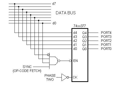
The key lies in the use of "illegal" (actually just NOP) opcodes in the _3 and _B columns of the opcode map.

As drawn below, the circuit responds to the one-cycle NOP's in both the _3 and _B columns of the opcode map. The lowest three bits of these opcodes always equal 011. And the high 5 bits are "Don't Care"... to the cpu, but not to us! :) :!:

All 32 of the _3 and _B column opcodes are single-cycle NOPs (except only 30 for WDC; see note below). These 1-byte, 1-cycle NOP's produce no dead cycles and are free of bizarre effects like those seen for undefined opcodes on NMOS. When a Col_3 or Col_B NOP appears in the instruction stream, the 'C02 will instantly swallow it and proceed to fetch another opcode on the immediately subsequent cycle. They truly are one-cycle NOPs, and all we have to do is...

  • detect them, and
  • capture the Don'tCare bits for our own use.

I've drawn the circuit as though implemented with 74xx building blocks, but programmable logic is an obvious alternative. In either case the key is simply to detect the coincidence of SYNC (indicating a 65c02 opcode fetch) with a certain binary pattern on the low bits of the data bus. The circuit detects binary xxxxx011 on the data bus. At the end of any such bus cycle, the high 5 bits of the data bus are copied all at once into the 74_377 register. For example, binary opcode 00000011 will output 00000 to the port, opcode 11111011 will output 11111 and so on.

Notice that this is not memory- mapped IO; no address space or address decoding is used.

Attachment:
Ultra-fast_65c02_output_port.gif
Ultra-fast_65c02_output_port.gif [ 4.69 KiB | Viewed 8500 times ]
One note regarding the 5-bit port:
  • unlike Rockwell's 'C02, the WDC W65C02S has 2 legitimate opcodes in the _B column: $CB (WAI) and $DB (STP). When using a WDC chip you'll probably wanna avoid executing those. And you may choose to avoid all of Column B, aiming for Column 3 only. This yields a 4-bit (not 5-bit) output port.


Notes pertaining to the 5-bit port:
  • the value that's output doesn't come from a CPU register. That's OK if you know in advance (ie; at assembly time) what value to output. But if the values are computed at run-time then you'll need to use self-modifying code or some sort of Case construct.
  • WDC details all the 65C02 NOPs, including multi-cycle NOPs and the one-cycle NOPs used here, in Table 7-1 of their 'C02 data sheet. From experiments I performed, I know all NOPs on the Rockwell 'C02 have the same behavior as WDC's, and it seems a virtual certainty that 'C02s from Synertek and other manufacturers are the same.
  • Interrupts will not be recognized while a one-cycle NOP (or a string of such NOP's) is executing. Interrupt are recognized on the first non-one-cycle instruction that follows. More info here.
  • For a fast port scheme that allows input as well as output, visit Garth's circuit potpourri page, here.

Finally, what would be the application for a circuit like this? The first thing that comes to my mind is accelerated Bank Switching ! Using the one-byte output instructions might be a great way of updating memory mapping circuitry. (In fact I think ElEctric EyE and I discussed this a while back -- and Nightmare Tony presently has an application as well.) I myself prefer to avoid bank switching, but there's no denying that in some situations it can be a satisfactory solution. And having a supremely small and fast output instruction helps!

-- Jeff


Last edited by Dr Jefyll on Tue Dec 19, 2023 1:52 pm, edited 7 times in total.

Top
 Profile  
Reply with quote  
 Post subject:
PostPosted: Fri Oct 07, 2011 9:13 am 
Online
User avatar

Joined: Fri Aug 30, 2002 1:09 am
Posts: 8428
Location: Southern California
Neat! Keep 'em comin'!


Top
 Profile  
Reply with quote  
 Post subject:
PostPosted: Fri Oct 07, 2011 1:56 pm 
Offline

Joined: Fri Jun 27, 2003 8:12 am
Posts: 618
Location: Meadowbrook
CLEVER. But then, your KimClone is also helluva clever. Garth, need a new section on such fun hacks set up on here, period.

Jeff: I would think of it as a 16 possible line (4 to 16) to allow for various functions, shaving off cycle time.

Almost thought it could work for the bankswitch command, but not sure how to use to shave off since it was designed for a single write to invoke.

LDA BankNum
STA BankRegister
Do operations in $6000-$7FFF banked area


Perhaps trap out a low usage opcode like you did on the KimClone to invoke this puppy?

_________________
"My biggest dream in life? Building black plywood Habitrails"


Top
 Profile  
Reply with quote  
PostPosted: Fri Oct 07, 2011 4:18 pm 
Offline
User avatar

Joined: Fri Dec 11, 2009 3:50 pm
Posts: 3349
Location: Ontario, Canada
Sorry for not explaining this more clearly. (I ran out of time when I was posting last night.) The value that's output doesn't come from a CPU register -- it comes from the opcode itself. Example:
Quote:
LDA BankNum
STA BankRegister
Do operations in $6000-$7FFF banked area [$6000-$7FFF is your "window" into the expanded space]
becomes
Code:
;---------------------------------------
SelectBank_00 MACRO          ;Macro that assembles a FastOutput instruction, data = $00
              db   00000011b ;binary opcode is the 5-bit data we want, with 011 appearing in the LSBs
              ENDM

SelectBank_01 MACRO          ;Macro that assembles a FastOutput instruction, data = $01
              db   00001011b ;binary opcode is the 5-bit data we want, with 011 appearing in the LSBs
              ENDM

            [ .... ]

SelectBank_1F MACRO          ;Macro that assembles a FastOutput instruction, data = $1F
              db   11111011b ;binary opcode is the 5-bit data we want, with 011 appearing in the LSBs
              ENDM
;---------------------------------------

                             ; (hypothetical application code)
              NOP            ; NOP, blah, blah, whatever!
              NOP
              NOP
              SelectBank_01   ;output updates Bank Register
              NOP             ;Do operations. Bank_01 appears in $6000-$7FFF banked area "window"
              NOP
              NOP

Of course you don't have to use macros; you could just db the wonky opcode bytes straight in when required. But the macros make for prettier code :D

-- Jeff


Top
 Profile  
Reply with quote  
 Post subject:
PostPosted: Fri Oct 07, 2011 8:12 pm 
Offline
User avatar

Joined: Mon Aug 08, 2011 2:48 pm
Posts: 808
Location: Croatia
Is it possible to make an illegal opcode detection, which triggers an nmi that would report an error?


Top
 Profile  
Reply with quote  
 Post subject: Stop, I say!
PostPosted: Fri Oct 07, 2011 9:26 pm 
Offline
User avatar

Joined: Thu May 28, 2009 9:46 pm
Posts: 8152
Location: Midwestern USA
Dajgoro wrote:
Is it possible to make an illegal opcode detection, which triggers an nmi that would report an error?

In theory, yes. In practice, it would be somewhat difficult. The 6502 doesn't respond to a hardware interrupt until the current instruction has been completed. So the mere act of asserting /NMI wouldn't do anything to stop the MPU from fetching the illegal opcode. Although I haven't given any thought to it, I suspect /RDY would have to be used to halt the processor, after which the processor would be somehow revectored to an error handler. It seems, to me, to be more trouble than it's worth.

Ironically, the one 65xx processor where intercepting an "illegal opcode" is easy is the 65C816, in which there are no illegal opcodes, even when running in 65C02 emulation mode.


Top
 Profile  
Reply with quote  
 Post subject:
PostPosted: Fri Oct 07, 2011 9:42 pm 
Offline
User avatar

Joined: Mon Aug 08, 2011 2:48 pm
Posts: 808
Location: Croatia
What about, when an illegal opcode is detected, would it be possible to assert rdy, and then somehow change the illegal instruction to a nop, and save the illegal instruction to a latch, that could be read. For example simulating 65c02 instructions using a regular nmos 6502 (i have only nmos 6502)?


Top
 Profile  
Reply with quote  
 Post subject:
PostPosted: Fri Oct 07, 2011 9:43 pm 
Offline
User avatar

Joined: Fri Dec 11, 2009 3:50 pm
Posts: 3349
Location: Ontario, Canada
BigDumbDinosaur wrote:
In theory, yes.
That's right, it is certainly possible. And the circuit would be quite simple (similar to what's shown above) if you will be satisfied with trapping only the 32 NOPs in column _3 and _B. (Specifically, $03, $13, $23 ... $F3 and $0B, $1B, $2B ... $FB.) But the 65C02 has fourteen other illegal/NOPs which aren't in columns _3 and _B. To also detect these would require a somewhat more complex circuit.

Either way, the question is: what is your goal? Why do you want to detect these? The "illegal" opcodes are actually harmless. But...
  • ordinarily they never occur, and when they do it may be a sign that your program has malfunctioned ("crashed"). In that case the NMI could at least halt the errant program (even though the error might not be recoverable).
  • A more ambitious goal would be to have the Interrupt Service Routine look back to determine which NOP had occurred. The ISR could then vector to a unique handler for each NOP, implementing a virtual instruction for each one. In other words each NOP would become a unique Software Interrupt.
BigDumbDinosaur wrote:
Although I haven't given any thought to it, I suspect /RDY would have to be used to halt the processor
Hmmm, maybe I'm missing something. But I don't see the need to halt the processor, or to prevent the NOP from executing either. But I guess I'm assuming it's OK if it's the following instruction that'd get pre-empted by the NMI. The ISR could easily backtrack (as long as we restrict ourselves to one-byte NOPs).

[Edit: my other assumption is that it's a CMOS chip, where the illegals can be allowed to execute harmlessly. NMOS would be a different story, and halting the CPU starts to make sense. Sorry for the double-take :oops: ]

-- Jeff


Last edited by Dr Jefyll on Fri Oct 07, 2011 10:20 pm, edited 1 time in total.

Top
 Profile  
Reply with quote  
 Post subject:
PostPosted: Fri Oct 07, 2011 9:47 pm 
Offline
User avatar

Joined: Fri Dec 11, 2009 3:50 pm
Posts: 3349
Location: Ontario, Canada
Dajgoro wrote:
What about, when an illegal opcode is detected, would it be possible to assert rdy, and then somehow change the illegal instruction to a nop, and save the illegal instruction to a latch, that could be read. For example simulating 65c02 instructions using a regular nmos 6502 (i have only nmos 6502)?
This is almost exactly what my KimKlone design does. But it has no need to assert RDY since the wiring allows op-code substitution in less than 50 ns -- without any need to extend the bus cycle.


Top
 Profile  
Reply with quote  
 Post subject:
PostPosted: Fri Oct 07, 2011 9:58 pm 
Offline
User avatar

Joined: Mon Aug 08, 2011 2:48 pm
Posts: 808
Location: Croatia
The idea is to enable the nmos 6502 to simulate 65c02 instructions.


Top
 Profile  
Reply with quote  
 Post subject:
PostPosted: Fri Oct 07, 2011 10:13 pm 
Offline
User avatar

Joined: Fri Dec 11, 2009 3:50 pm
Posts: 3349
Location: Ontario, Canada
OK, fair enough. I used a 32 by 8 TTL PROM to do the op-code substitution, and the same thing could work with your NMOS 6502. But the cost of parts would soon approach the price of a CMOS cpu. Is that OK? Is it the interesting challenge you want? Or would you rather have an actual 65C02? (I admit it sounds like a fun challenge conceiving an upgrade!)

The op-code substitution would be much harder if you wanted ALL illegal codes intercepted. My scheme only handles columns _3 and _B. It could also handle columns _7 and _F, which on NMOS are also illegal. But that's still not the entire list.

I need to think more about opcode substitution in that context. It's an interesting idea you propose.

-- Jeff


Top
 Profile  
Reply with quote  
 Post subject:
PostPosted: Fri Oct 07, 2011 10:55 pm 
Offline
User avatar

Joined: Mon Aug 08, 2011 2:48 pm
Posts: 808
Location: Croatia
In fact, the idea came to me when i was listening my operation systems class few days ago, and the professor mentioned that some more modern cpu would trigger an interrupt when an illegal opcode happens, so it could simulate non existing instructions that newer cpu might have, so why the 6502 would not be able to do that.
In my case it would only be necessary to trace 65c02 opcodes, i was thinking something simple and cheap might be possible.
There should be a 16 bit latch that would trap the address, and a logic that would detect 65c02 instructions,trigger a nmi, and change the instruction to a nop.
Maybe it would be best if a new topic is started, i feel like i hijacked this one...


Top
 Profile  
Reply with quote  
 Post subject:
PostPosted: Fri Oct 07, 2011 11:11 pm 
Online
User avatar

Joined: Fri Aug 30, 2002 1:09 am
Posts: 8428
Location: Southern California
In that case it would be much simpler to just drop a CMOS 6502 in the socket than to do the more-major modification to the hardware. The Commodore 64's 6510 is the only one I know of where you couldn't do that, since the 6510 was not made in CMOS.


Top
 Profile  
Reply with quote  
 Post subject:
PostPosted: Fri Oct 07, 2011 11:35 pm 
Offline
User avatar

Joined: Mon Aug 08, 2011 2:48 pm
Posts: 808
Location: Croatia
Then what about software triggered interrupt?


Top
 Profile  
Reply with quote  
 Post subject:
PostPosted: Sat Oct 08, 2011 4:44 pm 
Offline
User avatar

Joined: Fri Dec 11, 2009 3:50 pm
Posts: 3349
Location: Ontario, Canada
Dajgoro wrote:
Maybe it would be best if a new topic is started
Good idea -- let's do it. The new topic is Re-mapping Op-codes (eg: to create virtual instructions).

In the new topic,
Nightmaretony wrote:
I have an LED port on the pinball. By making 2 opcodes in CPLD logic, I can save operating cycles.


Old method:

LDA #$01
STA STATUSLED


Let me say that I can instead make 2 new opcodes such as TLH (Turn LED High) and TLL (Turn LED Low). This way, those would be single cycle instructions instead of needing to use 2 commands as I did before.

How can the Kowalski program use those, by macros?

It's the simulator you're referring to, right? I haven't used it, but presumably it would at least let you assemble the macro. The question is, what would it do when the time comes to "execute" the undefined opcode? Can anyone help us with this?

-- Jeff


Top
 Profile  
Reply with quote  
Display posts from previous:  Sort by  
Post new topic Reply to topic  [ 22 posts ]  Go to page 1, 2  Next

All times are UTC


Who is online

Users browsing this forum: GARTHWILSON, John West and 39 guests


You cannot post new topics in this forum
You cannot reply to topics in this forum
You cannot edit your posts in this forum
You cannot delete your posts in this forum
You cannot post attachments in this forum

Search for:
Jump to: