BigDumbDinosaur wrote:
Well, this project got stalled a bit, thanks to a defective part.

.
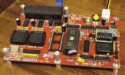
Parts received.
For some time, we've been kicking around various methods of wait-stating when a slow device must be accessed on an otherwise-fast machine. It has been noted that there are problems with using the RDY input to wait-state the MPU. As halting the MPU with RDY is tantamount to stopping the clock in the high phase, I proposed an
alternate wait-state method that involved stopping the Ø2 generator flip-flop in the high phase. That does work but requires an external timing device to set the duration of the wait-state.
More recently, Jeff (Dr. Jefyll) proposed another
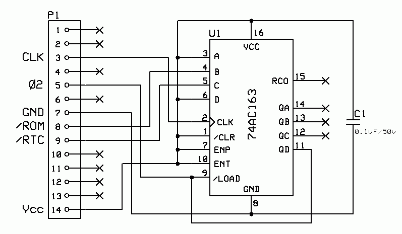
"stop the clock" method that makes use of a synchronous counter. Intrigued by the idea of doing it with a single chip solution, I decided to give it a test in POC V1.2, since that unit's purpose in life was to be a guinea pig. So I went to work and whipped up a circuit that accepted the chip select signals for the ROM and the RTC, the latter being the slowest I/O device, and pushed them through a AND gate to drive an input on the 'AC163.
While I was working out the details, Jeff and I kicked some E-mail back and forth on how to best do this, with he proposing that I ditch the AND gate and use several inputs on the 'AC163 in its place. The result of doing so would be a wait-state for one device would be slightly longer than for the other. In this application, that difference wouldn't matter, so I decided to go with Jeff's suggestion and ditch the gate. The resulting circuit looked like this:
Attachment:
File comment: Clock Stretcher Schematic
 clock_stretch_patch.gif [ 8.78 KiB | Viewed 19989 times ]
When neither the ROM or RTC is selected, the AC163s inputs are all high, which amounts to a preset value of $0F, causing the
QD output to follow the clock input at 1/2 its frequency—the change in outputs occurs on the rise of the clock. As
QD is where Ø2 is derived, Ø2 is likewise one-half the input clock rate.
If the ROM or RTC is selected, the corresponding input will be low and the preset value will be $0D (RTC) or $0B (ROM). Now the AC163 has to count more clock pulses to get to terminal count and flip Ø2 back to low. Ø2 will stay in the high phase longer, causing the CPU to wait.
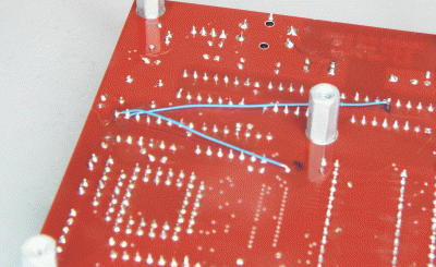
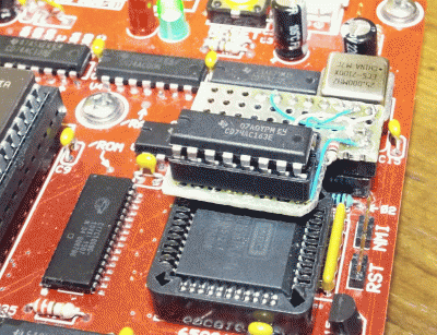
The design looked sound on paper, so I was ready to give it a try. The plan was to build this gadget on a small PCB, arranged so it could be plugged into the existing Ø2 flip-flop's socket. Some bodge wires
¹ would bring the ROM and RTC chip selects over to the socket on two otherwise unused pins.
Attachment:
File comment: Mainboard Circuit Patch
 mainboard_patch01.gif [ 5.37 MiB | Viewed 19989 times ]
The gadget would have to be pretty small to fit in the available space, in fact, not much bigger than the AC163 itself. The decision to build such a thing on a PCB was a concession to my deteriorated vision. However, Jeff offered to build the gadget for me on perf board, sparing me the time and expense of getting a PCB made, as well as the challenges of soldering small parts on a tiny board. The result looks like this:
Attachment:
File comment: Clock Stretcher Gadget Top View
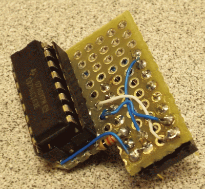 clock_stretcher01.gif [ 2.56 MiB | Viewed 19989 times ]
Attachment:
File comment: Clock Stretcher Gadget Bottom View
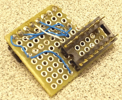 clock_stretcher02.gif [ 2.17 MiB | Viewed 19989 times ]
Cute little thing, eh?

Here's the stretcher gadget installed on POC V1.2:
Attachment:
File comment: Clock Stretcher Gadget on Mainboard
 mainboard_stretcher01.gif [ 3.32 MiB | Viewed 19989 times ]
Attachment:
File comment: Clock Stretcher Gadget on Mainboard
 mainboard_stretcher02.gif [ 4.54 MiB | Viewed 19989 times ]
With the hardware handled, it was time to do some testing and observe the circuit's behavior. The first step was to see if V1.2 would boot with the clock stretcher installed. Running on a 12.5 MHz Ø2 clock, V1.2 booted normally.
The next step was to acquire some data on what Ø2 was doing when a ROM or RTC access occurred. I burned a ROM with the following code:
Code:
toram =$002000
rtcbas =$00C300
rombas =$00d000
resvec =$00fffc
;
*=rombas
;
setup ldx #_tstend_-test-1
;
setup010 lda test,x
sta toram,x
dex
bpl setup010
;
jmp toram ;run test code
;
;
; test code...
;
test lda rombas ;gratuitous ROM access
nop
lda rtcbas ;gratuitous RTC access
bra test ;repeat
_tstend_ =*
All this does is copy a few lines of code to RAM and run it, causing the '816 to bang away at ROM and RTC. If everything is working, Ø2 will be a 50 percent duty cycle clock until access to either of those two devices occurs, at which time the high pulse should be elongated.
With that ROM installed, I hooked up the logic analyzer and captured the signals that were of interest:
Attachment:
File comment: Wait-State Testing
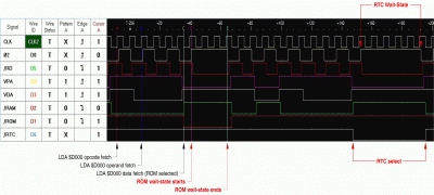 wait_stating.gif [ 112.49 KiB | Viewed 19989 times ]
Signal names are at the left end.
CLK is the "raw" clock signal being fed to the AC163 by the (25 MHz) clock oscillator. In the trace capture, it can be seen at the points where ROM and RTC are selected that the high phase of Ø2 is extended. Also,
VDA remains asserted for the duration of the wait-state, as does
/RD (read data). The MPU literally freezes in its tracks until the AC163 reaches terminal count and brings Ø2 low.
Also visible is the behavior of
VDA and
VPA as the MPU works through the code it is executing, plus the lag between the change in Ø2 and the other signals is quite clear.
The results of this experiment demonstrate that Jeff's solution of using a synchronous counter to stretch the clock is a sound one and one that is painless to implement.
Incidentally, if you try this, I recommend you use a 74AC163, not a 74HC163. The rise/fall times of the HC163's outputs may not meet WDC's specifications, possibly causing instability. Ringing with the AC163 may be a problem in some cases, which can be dampened with a series resistor connected as closely to the device's output as possible. You may have to experiment a bit to find the ideal resistance value. I used 100 ohms in V1.2, and Jeff added 22 ohms to the stretcher gadget. The signal as seen on my 'scope is pretty clean, with just a little ringing.
———————————————————
¹Thanks to British electronics enthusiasts for the term "bodge wire."
Edit: Fix some typos and stuff.


