6502.org Forum  Projects  Code  Documents  Tools  Forum
It is currently Sat Apr 27, 2024 11:28 pm

All times are UTC


Post new topic Reply to topic  [ 564 posts ]  Go to page Previous  1 ... 33, 34, 35, 36, 37, 38  Next
Author Message
PostPosted: Sat Sep 24, 2022 9:01 pm 
Offline
User avatar

Joined: Thu May 28, 2009 9:46 pm
Posts: 8147
Location: Midwestern USA
floobydust wrote:
Well, a quiz first thing in the morning.... I don't do well with morning exams, but....

I don’t do well with anything first thing in the morning. :D

Quote:
Looks like the pesky "$" signs in front of the commented section of Memory and I/O Block maps hosed up WinCUPL... but there is the extra commented part further down in the second file, but that wouldn't/shouldn't cause anything.

Passing grade??

Winner, winner, chicken dinner! Even though they are in a comment block, those dollar signs are fatal. If anything bound by /* and */ is a comment, why would WinCUPL be looking at comment content?

Y’know, dollars signs have been giving me problems for much of my life. :shock:

willie68 wrote:
i just processed your files with cupl itsself and it says...

Yep! Another bug in WinCUPL. Now, why am I not surprised?

Quote:
so $ in the first col means a preprocessor command for cupl. Even if it's in a comment, the preprocessor doesn't care about commands. To solve simply put a space before the $ sign...

I decided to just leave the dollar signs out, since it is apparent the values are hex.

I really wish Microchip would put someone to work going over these tools and fixing their problems. WinSim also has problems. I’ve had it report a simulation error on an unmodified file that had previously simulated without error, forcing me to terminate and restart the simulator. Probably a pesky memory leak somewhere.

_________________
x86?  We ain't got no x86.  We don't NEED no stinking x86!


Top
 Profile  
Reply with quote  
PostPosted: Mon Sep 26, 2022 12:25 am 
Offline
User avatar

Joined: Tue Mar 05, 2013 4:31 am
Posts: 1373
True enough... it would be nice if Microchip would put a bit of effort into WinCUPL to fix some of the bugs and issues. I recently had it corrupt two PLD projects... of course I had backups, and after deleting and reinstalling WinCUPL, all was back to normal, such as it is.

Needless to say, "anything" contained in a comment string should be ignored... :shock:

_________________
Regards, KM
https://github.com/floobydust


Top
 Profile  
Reply with quote  
PostPosted: Mon Sep 26, 2022 1:21 am 
Offline

Joined: Wed Jun 23, 2021 8:02 am
Posts: 165
BigDumbDinosaur wrote:
I really wish Microchip would put someone to work going over these tools and fixing their problems. WinSim also has problems. I’ve had it report a simulation error on an unmodified file that had previously simulated without error, forcing me to terminate and restart the simulator. Probably a pesky memory leak somewhere.


Why would they want to spend money maintaining a 30 year old product that is distributed free and is probably only used by hobbyists who don't buy large quantities of chips? There's just nothing in it for them. They would rather force everyone to spend a fortune on ProChipDesigner.


Top
 Profile  
Reply with quote  
PostPosted: Mon Sep 26, 2022 1:32 am 
Offline
User avatar

Joined: Thu May 28, 2009 9:46 pm
Posts: 8147
Location: Midwestern USA
kernelthread wrote:
Why would they want to spend money maintaining a 30 year old product that is distributed free and is probably only used by hobbyists who don't buy large quantities of chips? There's just nothing in it for them. They would rather force everyone to spend a fortune on ProChipDesigner.

I agree...financially it makes no sense. It’s like the situation with WDC’s 65C51 transmitter bug: a slow-selling product that will never be a money-maker.

_________________
x86?  We ain't got no x86.  We don't NEED no stinking x86!


Top
 Profile  
Reply with quote  
PostPosted: Mon Sep 26, 2022 2:21 am 
Offline
User avatar

Joined: Fri Aug 30, 2002 1:09 am
Posts: 8428
Location: Southern California
kernelthread wrote:
BigDumbDinosaur wrote:
I really wish Microchip would put someone to work going over these tools and fixing their problems. WinSim also has problems. I’ve had it report a simulation error on an unmodified file that had previously simulated without error, forcing me to terminate and restart the simulator. Probably a pesky memory leak somewhere.

Why would they want to spend money maintaining a 30 year old product that is distributed free and is probably only used by hobbyists who don't buy large quantities of chips? There's just nothing in it for them. They would rather force everyone to spend a fortune on ProChipDesigner.

I haven't been keeping up with this, but I will say that it was genius on Microchip's part to offer free development software and cheap programmers for their microcontrollers almost 30 years ago when they were coming up, and sell in hobbyist quantities, in a time when the other microcontroller manufacturers were charging heavily for tools and not "wasting their time" selling to hobbyists. [*] What happened is that a lot of hobbyists picked up the PIC microcontrollers and learned them, and then took them into their work projects which resulted in huge sales volumes. As for the employers and Microchip client companies, cost savings, training requirements (or lack thereof), and time to market motivated them to let their employees develop with a microcontroller they were already familiar with. It was a win for everyone but the competition.

[*] One manufacturer specifically told us in 1993 that our company was too small for them to be interested in working with us. That was National, with their COP800 line. That mentality apparently made them lose the microcontroller business.

_________________
http://WilsonMinesCo.com/ lots of 6502 resources
The "second front page" is http://wilsonminesco.com/links.html .
What's an additional VIA among friends, anyhow?


Top
 Profile  
Reply with quote  
PostPosted: Mon Sep 26, 2022 2:26 am 
Offline
User avatar

Joined: Tue Mar 05, 2013 4:31 am
Posts: 1373
I can agree that from a financial view, it doesn't make sense to fix WinCUPL. However, when people start looking at development tools, if a vendors "free" or trial versions are either buggy as hell and/or difficult to use, that will usually result in the end-user looking elsewhere for tools... and the same will likely go for hardware, especially if the hardware is proprietary and linked to their development tools. Who wants to spend a large amount of cash just to find out that the licensed version is every bit as bad as the trial or free version?

I think the larger issue these days is that most software companies are forcing a subscription model... so you always have defective/bug-infested code that you have to continuously pay for while the company strings their user base along. My son is a 3D Digital Animator/Technical Artist by trade. He's fed up with Adobe and AutoDesk, both of whom have gone to an expensive subscription model and their code is much worse now than ever before... and their current level of support is also horrible, to the point of being useless. You pay thousands every year and have the equivalent of alpha or beta level code to work with... crashes and all.

_________________
Regards, KM
https://github.com/floobydust


Top
 Profile  
Reply with quote  
PostPosted: Mon Sep 26, 2022 2:56 am 
Offline

Joined: Fri Dec 21, 2018 1:05 am
Posts: 1076
Location: Albuquerque NM USA
"Conservation of bugs" is one of those universal constants, so I rather work with older software that have known bugs than constantly updated software that fixed known bugs but introducing new (unknown) bugs. My lab computer runs Windows Vista; my CPLD design tool is Quartus version 8 which is about 20 years old; and my PCB tool is WinBoard/WinDraft whose last software update were 23 years ago.
Bill


Top
 Profile  
Reply with quote  
PostPosted: Mon Sep 26, 2022 1:57 pm 
Offline
User avatar

Joined: Thu May 28, 2009 9:46 pm
Posts: 8147
Location: Midwestern USA
JLCPCB has shipped the PCBs for POC V1.4, which I’m expecting to receive in about a week. All other parts needed to build the unit are on hand.

_________________
x86?  We ain't got no x86.  We don't NEED no stinking x86!


Top
 Profile  
Reply with quote  
PostPosted: Tue Nov 22, 2022 8:52 am 
Offline
User avatar

Joined: Thu May 28, 2009 9:46 pm
Posts: 8147
Location: Midwestern USA
Well, I’m behind the eight ball on updating this topic, but do have progress to report.

POC V1.4 is assembled to a point where I can run a NOP ROM in it and look at what is going on in the circuit.  Succinctly stated, it goes at 15 MHz, is unstable at 16 MHz, and blows at 20 MHz.  So 15MHz appears to be the Ø2 “ceiling” with this design.  Disappointing, needless to say, but something of value always seems to come out of failure.

Also, I made an interesting discovery involving power delivery to the unit, which I’ll get to before diving into the clock contretemps.

Here again are the schematic and PCB layout for the unit:

Attachment:
File comment: POC V1.4 Schematic
pocv140.pdf [377.59 KiB]
Downloaded 43 times
Attachment:
File comment: POC V1.4 PCB
poc_v14_pcb.gif
poc_v14_pcb.gif [ 411.99 KiB | Viewed 124121 times ]

First the power discovery...

As can be seen on the PCB layout, power is applied to the unit through a Berg connector, a standard part on 3-1/2" floppy disk drives.  Given its original application, one would expect it can easily handle the current required to run a POC unit.  So I had not given it any thought in that respect, since the POC version on which I started using it, V1.2, works, as does V1.3.

As I was analyzing the Ø2 ceiling problem, I decided to poke around a bit with the DMM to see how VCC looked.  At the power supply’s output, I got 5.09 volts under load.  However, at pin 1 of the Berg connector, which is where 5 volts comes in, I got 4.90 volts.  Granted, a loss of 190 millivolts in itself isn’t earth-shaking, but all my timing calculations assumed everything is powered at 5 volts.  So the thought had occurred that the Ø2 ceiling was due to the hardware running at slightly reduced voltage, which I’m now reasonably certain is not the case.

While contemplating this little discovery, I decided to find out where the loss was.  The power supply with which I’m testing doesn’t have a Berg plug, just the usual Molex type you see plugged into parallel-interface hard drives.  To make the connection to the POC unit, I’m using a commercially-made Molex-to-Berg adapter, which is nothing more than a Molex male connected to a Berg female through about 4 inches (102mm) of what appears to be 22 gauge wire.  It is in that adapter where those 190 millivolts are disappearing.

As for a cause, V1.4 has a 22V10 GAL to handle most of the glue logic.  GALs tend to be power hogs and thanks to the GAL, substantially more current is being drawn through the Molex-to-Berg adapter than with the older POC units.  Ergo some voltage loss.  In a bit of irony, POC V1.0 and V1.1 both had Molex receptacles for the power supply connection.  I replaced that item with the Berg connector to save PCB space and also because every time I go to unplug a Molex connector it becomes a struggle for my old, tired hands.  :shock:

Meanwhile, back to the Ø2 ceiling.  Below is an annotated logic analyzer trace of V1.4 coming up at 15 MHz:

Attachment:
File comment: POC V1.4 Boot @ 15 MHz
poc_v14_boot_15mhz.jpg
poc_v14_boot_15mhz.jpg [ 1.57 MiB | Viewed 124121 times ]

At that speed, everything appears to be copacetic, and in fact, periodic sampling of bus activity showed that the 65C816 was merrily working its way through a loop full of NOPs.

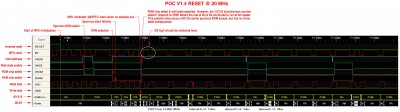
Now, here is another trace, this one of V1.4 coming up at 20 MHz:

Attachment:
File comment: POC V1.4 Boot @ 20 MHz
poc_v14_boot_20mhz.jpg
poc_v14_boot_20mhz.jpg [ 1.68 MiB | Viewed 124121 times ]

This time, the train goes into the ditch as soon as the MPU places the reset vector address ($00FFFC) on the bus.  The 74AC163 counter fails to react in time to /WSE (wait-state enable) being asserted and Ø2 continues to run at full speed for another cycle.  The ROM can’t keep up, the MPU gets a garbage address and it’s all down hill after that.  Adding to the fun, the AC163 does finally respond to /WSE during the low phase of the next clock cycle, definitely a case of locking the barn doors after the cows have wandered off.

As a harbinger of things to come, note system behavior when the spurious ROM select occurs as the MPU is going through initialization following the clearing of reset (three cycles after reset clears).  The AC163’s behavior is identical to what happens when the MPU is finally ready.  Clearly there is a timing issue involving the AC163 and how quickly it can react when /WSE is asserted.  My analysis may be off to some degree and I fully expect attempts to shoot big holes in it.  :D  But, here goes...

POC V1.2 was the first unit in which I used the AC163 as a clock source.  You may recall that it was an exact adaption of Jeff’s clock-stretching circuit described here (in fact, he built the module for me).  V1.2 was stable at 20 MHz, although a more detailed look at things now indicates the AC163 I used in that unit was punching well above its weight class.  In any case, there was no extended RAM in that unit, which made the glue logic less complex than later units, with a correspondingly-reduced prop delay.  The glue logic could assert /WSE more rapidly, which when combined with an AC163 running substantially better than specs, made it work.

According to the AC163 data sheet, tsu, which is the required setup time for the A through D inputs before the clock input goes high, is 4.4ns minimum, operating on 5 volts and anywhere within the commercial temperature range.  That is, as long as an A-D input is stable at least 4.4ns before the rise of the clock, things will work.  That timing margin seems manageable until you consider that tsu is relative to the 40 MHz oscillator driving the clock input.  In other words, the 4.4ns minimum is relative to the 12.5ns half-cycle period of the oscillator.  At that speed, the timing margin available to satisfy tsu would be 12.5 - 4.4 or 8.1ns.  So at first blush, it would appear things ought to work.

In this application, the AC163’s B input is controlled by /WSE, the latter which is generated by the GAL.  The GAL I’m using, a Microchip ATF22V10C, is rated at 7.5ns tpd pin-to-pin.  All logic in the GAL is combinatorial, so the worst-case prop delay from when the MPU does something until the GAL’s outputs reflect the change will be 7.5ns.  That would seem to be within the previously-quoted 8.1ns margin available to meet tsu.  However, here comes the “gotcha”...several of them, actually.  :twisted:

The MPU is running at 20 MHz, not 40, which means the GAL is reacting to events that occupy two oscillator cycles, not one.  That 8.1ns margin I earlier mentioned is relative to the 40 MHz half-cycle period, which is 12.5ns.  The Ø2 half-cycle period is 25ns, which effectively makes the 8.1ns look like 4.05ns for timing purposes.  The GAL can’t respond in 4ns, so it is unable to assert /WSE quickly enough to meet the tsu deadline.

Above, I said there were several “gotchas.”  The other one, which appears to be the final nail in the coffin, is the AC163’s tpd, which is the prop time from when the (oscillator) clock goes high until a change is seen at any Q output.  The worst-case for tpd running on 5 volts is 9.4ns.  The logic analyzer says the AC163 in V1.4 is running right around 6ns—“punching above its weight class.”  Hence a Ø2 phase change lags an oscillator cycle by a more-or-less constant 6ns, which further messes up timing.

Given what I’ve learned from this, I’m less confident in the synchronous counter method of generating a stretchable clock, at least in a circuit that is intended to run faster than 15 MHz.  The logic analyzer traces show that while the GAL can quickly assert /WSE in response to the address on the bus, the timing is too skewed relative to the oscillator to be reliable at high speeds.  At 15 MHz, the GAL in V1.4 takes only 4ns from the time the MPU drives the address bus until /WSE is asserted.  Unfortunately, that looks like 8ns from the perspective of the AC163, since its timing is slaved to the oscillator’s signal, not Ø2.  The 6ns skew from the oscillator to Ø2 aggravates the situation by making it look like 14ns to the AC163.  Hence the results.

It looks like it’s back to the metaphoric drawing board.  :roll:

_________________
x86?  We ain't got no x86.  We don't NEED no stinking x86!


Last edited by BigDumbDinosaur on Mon Nov 06, 2023 12:30 pm, edited 2 times in total.

Top
 Profile  
Reply with quote  
PostPosted: Tue Nov 22, 2022 9:33 am 
Offline
User avatar

Joined: Thu Dec 11, 2008 1:28 pm
Posts: 10793
Location: England
Hmm, I don't understand this bit:
> The MPU is running at 20 MHz, not 40, which means the GAL is reacting to events that occupy two oscillator cycles, not one. That 8.1ns margin is based upon the 40 MHz half-cycle period, which is 12.5ns. The Ø2 half-cycle period is 25ns, which effectively makes the 8.1ns look like 4.05ns.

I wonder, is there another way to describe this, or draw it out?


Top
 Profile  
Reply with quote  
PostPosted: Tue Nov 22, 2022 11:10 am 
Offline

Joined: Wed Jun 23, 2021 8:02 am
Posts: 165
I think the extra piece of the puzzle is the propagation delay from 74AC163 clock high to processor PHI2 low.
From your schematic the worst case timing path is as follows:
(i) 74AC163 clock high to QD low
(ii) 65C816 PHI2 low to address valid
(iii) 74AC573 input to output propagation (for A16)
(iv) 22V10 input to output propagation (An to WSE)
(v) 74AC163 setup time B valid to clock high

From the data sheets (or reasonable guesses) these values are (typical, worst case):

Code:
(i)    5.5     9.5
(ii)  10.0    15.0
(iii)  5.5     7.5
(iv)   4.4     7.5
(v)    4.0    10.5

Tot   29.4    50.0


So your circuit's typical max frequency is 1/29.4ns which is ~34MHz, so 17MHz CPU clock.
Worst case timings give max frequency 1/50ns = 20MHz, so 10MHz CPU clock.

My suggestion would be to use a CPLD and try to put everything - the clock divider, clock stretch logic and address decoding on there.


Top
 Profile  
Reply with quote  
PostPosted: Tue Nov 22, 2022 11:12 am 
Offline
User avatar

Joined: Thu May 28, 2009 9:46 pm
Posts: 8147
Location: Midwestern USA
BigEd wrote:
Hmm, I don’t understand this bit:
> The MPU is running at 20 MHz, not 40, which means the GAL is reacting to events that occupy two oscillator cycles, not one. That 8.1ns margin is based upon the 40 MHz half-cycle period, which is 12.5ns. The Ø2 half-cycle period is 25ns, which effectively makes the 8.1ns look like 4.05ns.

I wonder, is there another way to describe this, or draw it out?

It is kind of hard to explain clearly. I’m reasonably confident I understand what’s going on, but seem to be having difficulty articulating it.

Since the AC163 looks like a D-flop the way it is connected, its QD output, from which Ø2 is derived, makes one transition for every two low-to-high transitions at the clock input. Under normal operation, the A-D inputs are held high, and Ø2 is one-half the frequency of the oscillator, with a 50 percent duty cycle. When the B input is driven low while QD is low (corresponding to Ø2 low), the next low-to-high clock transition will cause QD to go high and remain so until two more low-to-high clock transitions occur, this being due to the AC163 being a counter, not just a bunch of flops. Hence the clock is stretched by one Ø2 cycle. That’s the easy part. :D

The tricky part is in driving B low at the right time relative to both Ø2 and the clock input. All timing in the AC163 is measured relative to the clock input only. There are two things at work here: tSU, which is the A-D input setup time before the clock goes high, and tPD, which is the elapsed time from when the clock goes high to when the Q outputs change state.

Since two full clock input cycles are needed to produce one unstretched Ø2 cycle, timing from the perspective of the GAL, which is responding to address bus transitions occurring at Ø2 speeds, is effectively tSU ÷ 2, not tSU. When that is coupled with tPD, tSU effectively becomes tSU ÷ 2 - tPD.

tSU and tPD, of course, will vary from part to part. While tSU will never be worse than the minimum specified in the data sheet and therefore can be thought of as a constant for timing purposes, tPD can be as slow as 15ns or as fast as 4.2ns. Such a wide range makes it hard to predict how well the AC163 will work in a given timing scenario.

Did this explanation make more sense?

_________________
x86?  We ain't got no x86.  We don't NEED no stinking x86!


Top
 Profile  
Reply with quote  
PostPosted: Tue Nov 22, 2022 11:47 am 
Offline

Joined: Wed Jun 23, 2021 8:02 am
Posts: 165
Or, another possibility is to use RDY for wait states instead of clock stretching. That gives an extra half cycle for the circuit to figure out if wait states are needed, at the expense of a more complicated circuit to generate the bank latch enable signal.


Top
 Profile  
Reply with quote  
PostPosted: Tue Nov 22, 2022 12:01 pm 
Offline
User avatar

Joined: Thu May 28, 2009 9:46 pm
Posts: 8147
Location: Midwestern USA
kernelthread wrote:
I think the extra piece of the puzzle is the propagation delay from 74AC163 clock high to processor PHI2 low.

Did you read all of my write-up? I did describe how the 163’s tPD skews Ø2 relative to the oscillator.

Quote:
From your schematic the worst case timing path is as follows:
(i) 74AC163 clock high to QD low

That is a wide range. The TI data sheet I have says anywhere from 4.2ns to 15ns on 5 volts over the full commercial temperature range.

Quote:
(ii) 65C816 PHI2 low to address valid

The 816 I’m using in V1.4 is consistently driving the address 12ns after the fall of Ø2. I looked at analysis I did on POC 1.3 when I built it and was seeing 11ns. In general, the timings specified in the 816’s data sheet are pessimistic, and likely reflect the capabilities of the Sanyo 0.8µ cores that were used long ago (all product since around 2006 is 0.6µ).

Quote:
(iii) 74AC573 input to output propagation (for A16)

In this particular test, that isn't a factor, since code is being executed only in bank $00. The latch’s Dx to Qx prop time only matters if Dx changes state on the next Ø2 low half-cycle.

Quote:
(iv) 22V10 input to output propagation (An to WSE)

That would be 7.5ns, worst-case. The GAL in V1.4 is running in the range of 4-6ns.

Quote:
(v) 74AC163 setup time B valid to clock high

That would be 4.4ns, worst-case.

Quote:
So your circuit's typical max frequency is 1/29.4ns which is ~34MHz, so 17MHz CPU clock.
Worst case timings give max frequency 1/50ns = 20MHz, so 10MHz CPU clock.

It’s unstable at 16 MHz, as I explained above.

Quote:
My suggestion would be to use a CPLD and try to put everything - the clock divider, clock stretch logic and address decoding on there.

I’m ahead of you on that. POC V2.0 uses a CPLD to implement most of that stuff.

Quote:
Or, another possibility is to use RDY for wait states instead of clock stretching. That gives an extra half cycle for the circuit to figure out if wait states are needed, at the expense of a more complicated circuit to generate the bank latch enable signal.

That has been discussed at length in other topics. See here for some discussion on the foibles of using RDY, especially with the 816.

_________________
x86?  We ain't got no x86.  We don't NEED no stinking x86!


Top
 Profile  
Reply with quote  
PostPosted: Tue Nov 22, 2022 1:53 pm 
Offline

Joined: Wed Jun 23, 2021 8:02 am
Posts: 165
You could get the benefit of RDY without the hassles by using a more complicated state machine for clock stretch.
Suppose you have 4 states S0-S3, S0 is the initial state. The state machine is clocked by your double-frequency oscillator.
The transitions are:
S0 always goes to S1
S1 goes to S0 if WSE is not asserted, S2 if it is
S2 always goes to S3
S3 always goes to S0
The CPU clock is high in S1, S2, S3 and low in S0.
That would give you the same clock stretching behaviour as now, but you have until the point where the unstretched clock would fall (minus a setup time) to generate the WSE signal.

This could be implemented using the AC163 plus a couple of gates:

input D = 0
inputs A,B,C = 1
QD feeds PHI2
/LOAD = !(QD & \WSE) & !QB

So the counter starts with count 7, counts up to 8 then reloads 7 if WSE is not asserted. If WSE is asserted it counts up to 9 then 10, then reloads 7, thus stretching the high phase by 2 oscillator clocks. By rejigging things a bit you might be able to put the /LOAD logic into the 22V10.


Top
 Profile  
Reply with quote  
Display posts from previous:  Sort by  
Post new topic Reply to topic  [ 564 posts ]  Go to page Previous  1 ... 33, 34, 35, 36, 37, 38  Next

All times are UTC


Who is online

Users browsing this forum: No registered users and 23 guests


You cannot post new topics in this forum
You cannot reply to topics in this forum
You cannot edit your posts in this forum
You cannot delete your posts in this forum
You cannot post attachments in this forum

Search for:
Jump to: