6502.org Forum  Projects  Code  Documents  Tools  Forum
It is currently Sun May 05, 2024 1:21 am

All times are UTC


Post new topic Reply to topic  [ 564 posts ]  Go to page Previous  1, 2, 3, 4, 5, 6, 7 ... 38  Next
Author Message
 Post subject:
PostPosted: Tue Nov 10, 2009 4:54 am 
Offline
User avatar

Joined: Thu May 28, 2009 9:46 pm
Posts: 8173
Location: Midwestern USA
Nightmaretony wrote:
If you can find a place to manufacture cheap from Gerbers, may I recommend Kicad?

I haven't found such a place but did download Kicad. As soon as time is available I'll monkey with it and see how it works.

_________________
x86?  We ain't got no x86.  We don't NEED no stinking x86!


Top
 Profile  
Reply with quote  
 Post subject: POC Computer
PostPosted: Sat Nov 21, 2009 3:11 am 
Offline
User avatar

Joined: Thu May 28, 2009 9:46 pm
Posts: 8173
Location: Midwestern USA
Argghhhh!!!!!

I got the PCBs to build my POC computer and prepared to populate the first one. The slobbering iron was good and hot, my 5-diopter work light was ablazin' and the logic probe and 'scope were trembling with excitement. I reached for my Olympus Camedia camera to take a series of pics as I slobbered parts to the board, just so others could see that if a big, broken-down old dinosaur with claws instead of fingers can do it, anyone could do it, even an untrained monkey.

Unfortunately, my camera decided to go belly-up and won't power on, even with fully recharged batteries. I tried everything I could think, including using my extensive...er...vocabulary to describe the camera. I even considered treating it as a football and sending it flying across the shop. Nothing! The thing just won't work anymore. Cheap piece of crap!!! Olympus should call the thing Camodia instead of Camedia.

Argghhhh!!!!!

Anyhow, I'll get another camera and then will have a few pics. I don't intend to let this momentous (?) occasion slip by without some sort of photographic record, especially the part where I put the juice to the board and something goes sizzle-pop-bang! :D

Argghhhh!!!!!

_________________
x86?  We ain't got no x86.  We don't NEED no stinking x86!


Top
 Profile  
Reply with quote  
 Post subject:
PostPosted: Sat Nov 21, 2009 5:10 am 
Offline

Joined: Sat Jan 04, 2003 10:03 pm
Posts: 1706
I have an Olympus Camedia camera too, and it still works fine after all these years. However, I've been storing it with the batteries removed. I do this in my feeble attempts at keeping the charge on the batteries as long as possible. But, it sounds like it might have a beneficial impact on camera longevity as well.

hmm...


Top
 Profile  
Reply with quote  
 Post subject:
PostPosted: Sun Nov 22, 2009 4:41 am 
Offline
User avatar

Joined: Thu May 28, 2009 9:46 pm
Posts: 8173
Location: Midwestern USA
kc5tja wrote:
I have an Olympus Camedia camera too, and it still works fine after all these years. However, I've been storing it with the batteries removed. I do this in my feeble attempts at keeping the charge on the batteries as long as possible. But, it sounds like it might have a beneficial impact on camera longevity as well.

hmm...

I've done the same with mine, for the same reason (evidently a clock or something in the camera is a bit power-hungry). Obviously, doing so didn't add any life to the hunk of junk. Mine was a 2 megapixel unit, so maybe it was time anyhow to get something a bit more current.

It could have been worse. Suppose I had gotten the photos and then later, when I went to transfer them to the computer, the Camodia had decided to go kaput? That would have been far more aggravating, possibly tempting me to take the camera to the nearby UP mainline and let Amtrak, which comes by several times per day at high speed, to deal with it. :twisted:

_________________
x86?  We ain't got no x86.  We don't NEED no stinking x86!


Top
 Profile  
Reply with quote  
 Post subject: Dead Camodia
PostPosted: Sun Nov 22, 2009 4:42 am 
Offline
User avatar

Joined: Thu May 28, 2009 9:46 pm
Posts: 8173
Location: Midwestern USA
kc5tja wrote:
I have an Olympus Camedia camera too, and it still works fine after all these years. However, I've been storing it with the batteries removed. I do this in my feeble attempts at keeping the charge on the batteries as long as possible. But, it sounds like it might have a beneficial impact on camera longevity as well.

hmm...

I've done the same with mine, for the same reason (evidently a clock or something in the camera is a bit power-hungry). Obviously, doing so didn't add any life to the hunk of junk. Mine was a 2 megapixel unit, so maybe it was time anyhow to get something a bit more current.

It could have been worse. Suppose I had gotten the photos and then later, when I went to transfer them to the computer, the Camodia had decided to go kaput? That would have been far more aggravating, possibly tempting me to take the camera to the nearby UP mainline and let Amtrak, which comes by several times per day at high speed, to deal with it. :twisted:

_________________
x86?  We ain't got no x86.  We don't NEED no stinking x86!


Top
 Profile  
Reply with quote  
 Post subject: Re: POC Computer
PostPosted: Sun Dec 20, 2009 7:28 pm 
Offline
User avatar

Joined: Thu May 28, 2009 9:46 pm
Posts: 8173
Location: Midwestern USA
BigDumbDinosaur wrote:
Unfortunately, my (Camedia) camera decided to go belly-up...

Christmas came a little bit early and I now have a new camera to take pictures as I build up POC 1.0. First step will be to see if I can actually slobber the SRAM to the PCB. Them there SOJ32 packages look mighty small, even under magnification. :) Well, I do have four PCBs and an equal number of SRAMs to booger up. :D

BTW, prior to submitting the PCB to the board house, I had rearranged the layout to tighten up things. The board is now 6 inches by 3.25 inches (19.5 sqaure inches). I was able to shrink the length of the address and data line traces, which should keep a lid on reactive issues. At this point, I believe the upper limit on clock speed will be the setup time required by the Dallas 1511 watchdog timer. Computations suggest 8 MHz as the limit, but that may turn out to be a little optimistic. 'Twill be interesting...

PCB Layout

Checking Component Placements (photographed through 5-diopter magnification)

Memory Map

MPU Interface

RAM, ROM & I/O

External Interface

_________________
x86?  We ain't got no x86.  We don't NEED no stinking x86!


Last edited by BigDumbDinosaur on Tue Dec 22, 2009 7:44 pm, edited 4 times in total.

Top
 Profile  
Reply with quote  
 Post subject: Re: POC Computer
PostPosted: Sun Dec 20, 2009 9:42 pm 
Offline

Joined: Tue Jul 05, 2005 7:08 pm
Posts: 991
Location: near Heidelberg, Germany
BigDumbDinosaur wrote:
'Twill be interesting...


Yes, it will :-)

You've left out some parts of the schematics I think. I am wondering, do you have any more RDY logic or do you run all parts with CPU clock speed?

A naming thing: WD and /WD are named as if one is the inverted signal of the other - but /WD is qualified by Phi2, while WD is not. I found such naming to easily be source of problems when you just mess them up, or you later need a real inverted version of one of those signals.

Looking forward to your results!

André


Top
 Profile  
Reply with quote  
 Post subject: Re: POC Computer
PostPosted: Sun Dec 20, 2009 10:50 pm 
Offline
User avatar

Joined: Thu May 28, 2009 9:46 pm
Posts: 8173
Location: Midwestern USA
fachat wrote:
You've left out some parts of the schematics I think. I am wondering, do you have any more RDY logic or do you run all parts with CPU clock speed?

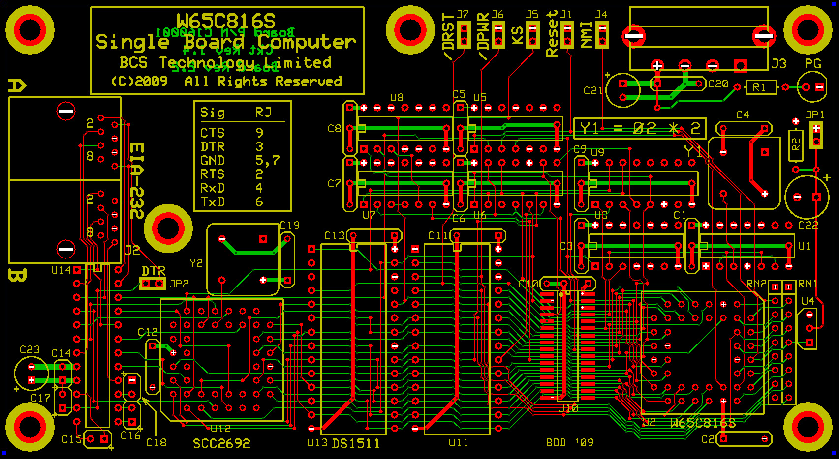
Everything is running at the MPU clock speed in this first design. I'll initially bring it up on 1 MHz (2 MHz oscillator) to verify that it's upright with a pulse. Assuming it gets through that, I'll ramp up the clock rate until something messes up. Most likely, the speed limiter will be the DS1511 timekeeper. The EPROM is rated at 70ns and the SRAM at 12ns, so I don't expect that they'll be a concern. Past experience with Dallas Semi's timekeepers, however, indicates that they are quite slow, especially during write ops.

Once this design is working I'll develop another design that can wait-state peripheral access. On that unit, I'll try running the clock speed up to the max to see what happens.

Quote:
A naming thing: WD and /WD are named as if one is the inverted signal of the other - but /WD is qualified by Phi2, while WD is not. I found such naming to easily be source of problems when you just mess them up, or you later need a real inverted version of one of those signals.

I agree the naming could be a bit confusing. The WD signal is an inversion of the MPU's RWB. WD, as you probably noted, is used to gate output enable on memory or I/O. So, disregarding the Ø2 qualification applied to /WD, WD is the inversion of /WD. Perhaps I should rename WD to /RWB. :)

Quote:
Looking forward to your results!

André

It will all be posted here, good or not-so-good. :) 
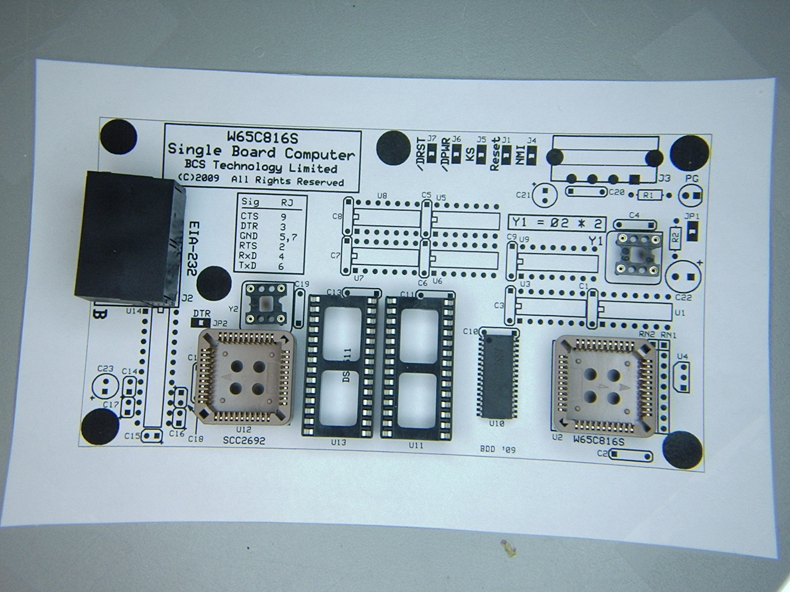
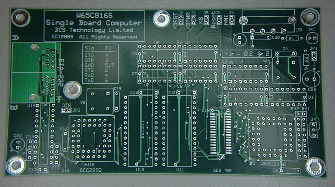
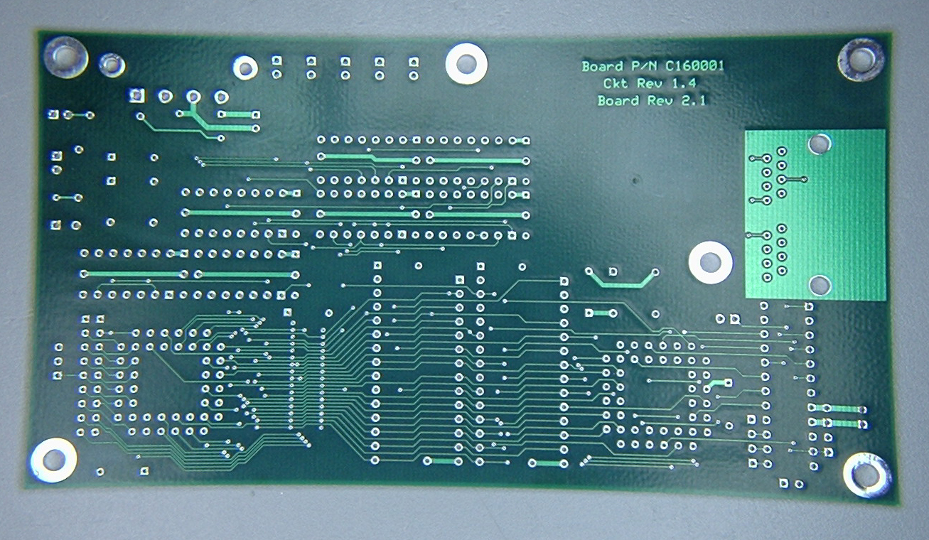
I will have some pictures of the board as I populate it, as well as some 'scope shots if I see life after applying power. Assuming the unit doesn't fill up my shop with nasty-smelling smoke and activity is present on the address and data lines, I will then connect one of my old WYSE 60 terminals to EIA-232 port A. Following reset, code in the EPROM should write some text to the terminal screen and spin in an input loop looking for some keyboard input.

As I said when I started this topic, I've worked with this stuff literally for decades but have never scratch-designed and built a computer (excepting a relay computer I built while in high school). This Proof Of Concept design will mostly prove that I know what I'm doing...or not!

_________________
x86?  We ain't got no x86.  We don't NEED no stinking x86!


Top
 Profile  
Reply with quote  
 Post subject: POC V1.0 Computer
PostPosted: Tue Dec 22, 2009 7:28 pm 
Offline
User avatar

Joined: Thu May 28, 2009 9:46 pm
Posts: 8173
Location: Midwestern USA
Here are a few pictures of the printed circuit board, photographed through 5-diopter magnification. Signal traces are 0.006 inches wide, so knowing that will give you some idea of scale. The small-outline component to the immediate left of the '816 PLCC socket is the 128Kb x 8 SRAM (SOJ32). That'll be the first item to get soldered to the board. Everything else will be simple by comparison. I may not get going on this until after Christmas, as too many things are demanding my time right now. :D

Component Side of Bare PCB

Solder Side of Bare PCB

_________________
x86?  We ain't got no x86.  We don't NEED no stinking x86!


Last edited by BigDumbDinosaur on Wed Dec 23, 2009 1:07 am, edited 1 time in total.

Top
 Profile  
Reply with quote  
 Post subject:
PostPosted: Wed Dec 23, 2009 12:31 am 
Offline

Joined: Thu Jul 26, 2007 4:46 pm
Posts: 105
In future, can I suggest doing a ground pour of the board? It will probably help with increasing the operating frequency.


Top
 Profile  
Reply with quote  
 Post subject:
PostPosted: Wed Dec 23, 2009 1:01 am 
Offline
User avatar

Joined: Fri Aug 30, 2002 1:09 am
Posts: 8432
Location: Southern California
Quote:
In future, can I suggest doing a ground pour of the board? It will probably help with increasing the operating frequency.

It appears to be a multilayer board with internal power and ground planes, which is far better than pours. [Edit, 12 years later: There is a way to use them to supplement real planes; but if they're not done correctly, they can actually make things worse, according to experts in the field like Rick Hartley, Eric Bogatin, and Suzie Web whose lectures you can see on Altium's YouTube channel.]

_________________
http://WilsonMinesCo.com/ lots of 6502 resources
The "second front page" is http://wilsonminesco.com/links.html .
What's an additional VIA among friends, anyhow?


Top
 Profile  
Reply with quote  
 Post subject:
PostPosted: Wed Dec 23, 2009 1:31 am 
Offline
User avatar

Joined: Thu May 28, 2009 9:46 pm
Posts: 8173
Location: Midwestern USA
GARTHWILSON wrote:
Quote:
In future, can I suggest doing a ground pour of the board? It will probably help with increasing the operating frequency.

It appears to be a multilayer board with internal power and ground planes, which is far better than pours.

Garth is correct: this is a 4-layer board with inner power and ground planes.

I'm presuming what is being referred to as a "ground pour" is what technically referred to as an filled plane (a filled plane can also be a power plane if desired). While filled planes can reduce noise radiation and act as power and ground paths, they add a lot of distributed capacitance, increasing the rise and fall time of high rate digital signals. I would use filled planes on something handling low speed logic and thus avoid the extra cost of a 4-layer design, but not on a design where the clock rate will be in the multiple megahertz range.

Aside from the shielding and decoupling effects of inner power and ground planes, a big advantage of such a layout is not having to route power and ground to everything, thus allowing a more compact layout.

On this design, the only places where I have have filled planes is around the dual RJ45 jack to help prevent high frequency noise from leaking into the EIA-232 connections.

_________________
x86?  We ain't got no x86.  We don't NEED no stinking x86!


Top
 Profile  
Reply with quote  
 Post subject:
PostPosted: Wed Dec 23, 2009 5:21 am 
Offline
User avatar

Joined: Fri Aug 30, 2002 1:09 am
Posts: 8432
Location: Southern California
Digital circuits, in spite of the megohms-high DC resistances of CMOS inputs, act as low-impedance circuits in the high frequencies whose harmonics can go, not unrealistically, into hundreds of MHz even in a 65c02 system, and many GHz in high-end processor boards. Most noise problems in low-impedance circuits are caused my magnetic-field (ie, inductive) coupling as opposed to electric-field (ie, capacitive) coupling, the latter being more of a problem in high-impedance circuits. Pours help especially in boards of only one or two layers to reduce crosstalk from capacitive coupling, terminating electric-field lines to the grounded metal before those field lines reach a nearby potential victim circuit. If you have a true ground plane, this is already done, so pours don't really help anything. There's more to it though. [Edit, 12 years later: There is a way to use pours to supplement real planes; but if they're not done correctly, they can actually make things worse, according to experts in the field like Rick Hartley, Eric Bogatin, and Suzie Web whose lectures you can see on Altium's YouTube channel.]

A big advantage to a continuous ground plane is that it eliminates inductance in the ground connections on the board itself, provided the plane is continuous. If the plane had a few cuts in it to allow traces through, that effect is partially lost.

Another advantage is that as a trace goes over the plane, the high-frequency return current travels through the ground plane not all over, but immediately under the trace, following the shape of the trace. The effect is that for any given location on the trace, there's the same amount of current flowing in both directions a few thousandths of an inch apart, preventing the radiation of noise and the susceptibility to noise, and cutting the trace inductance way down. But if the trace has to cross a thin cut in the plane such that the return signal current has to take a detour of say an inch or two, then the trace again becomes an antenna, even though 99% of it is against the ground plane. This is, in fact, how some antennas are made in things like cell phones.

Putting a capacitor from a power pin of an IC to the ground plane, right there at the pin, improves the high-frequency bypassing, keeping a steadier voltage at the power pin, which makes for steadier outputs at pins that are supposed to be at a logic high. The steadier Vcc may affect input threshold levels too. Capacitors aren't perfect though, especially ones with leads, as the leads add series inductance and lower the frequency beyond which the capacitor's reactance again starts climbing. If there's a power plane as well, not only is the iductance of the power connection in the board itself eliminated, but it has an inductance-free capacitance to the ground plane. In boards that have to be ultra quiet, sometimes a technology is used where they purposely have only .002" to .004" of insulation and distance between the two planes inside the board, in order to increase the inductance-free capacitance between the planes. (If you're thinking ahead, you'll quickly get to why PLCCs, PQFPs, and down are much more suitable for high-speed digital than DIPs are.)

If you get really interested in this stuff, get Dr. Howard Johnson's book, called "High-Speed Digital Design: A Handbook of Black Magic" It has 447 pages. I haven't seen it, but I've kept loads of his articles over the years. Most of them are about things that hardly have any application in home-made 6502 circuits (like one one I have in front of me at the moment is about designing controlled-impedance vias), but they do improve one's understanding of what we're up against in the digital world (unless you're happy to just use 1 or 2MHz parts).

I worked in VHF and UHF power transistor applications engineering in the mid-1980's. I swore I'd never do RF again, but the knowledge has helped some in digital, mixed-signal, and switch-mode power supplies, and doggonit if I wasn't doing some design at 2.5GHz again last month! If you had told me ten years ago that there was such thing as a chip antenna, I would have thought it was a joke.

_________________
http://WilsonMinesCo.com/ lots of 6502 resources
The "second front page" is http://wilsonminesco.com/links.html .
What's an additional VIA among friends, anyhow?


Top
 Profile  
Reply with quote  
 Post subject:
PostPosted: Wed Dec 23, 2009 5:37 am 
Offline
User avatar

Joined: Thu May 28, 2009 9:46 pm
Posts: 8173
Location: Midwestern USA
GARTHWILSON wrote:
Most noise problems in low-impedance circuits are caused my magnetic-field (ie, inductive) coupling as opposed to electric-field (ie, capacitive) coupling, the latter being more of a problem in high-impedance circuits.

That's correct. Inductive effects can also raise nasty problems on power and ground traces of any length, which is where having inner ground and power layers really helps.

However, distributed capacitance and signal skew on longer traces are what can cause a circuit to misbehave for no apparent reason as the clock frequency gets ramped up. The problem, of course, is either produces a lazy transition from one logic state to the other. As I was doing my layout I was trying to use minimum length routing and minimize the use of via. Of course, no dense layout can be done without via, so the other trick I used was extra small via, which introduce less inductance into the circuit. Inductance, of course, can increase skew time.

In my design, there are no breaks in either inner layer to accommodate traces. There are, of course, via that pass through without contacting either inner layer, but they should have minimal effect on board performance.

Quote:
If you get really interested in this stuff, get Dr. Howard Johnson's book, called "High-Speed Digital Design: A Handbook of Black Magic."

I haven't read his book but have perused more than a few of his articles over the years. :)

_________________
x86?  We ain't got no x86.  We don't NEED no stinking x86!


Top
 Profile  
Reply with quote  
Display posts from previous:  Sort by  
Post new topic Reply to topic  [ 564 posts ]  Go to page Previous  1, 2, 3, 4, 5, 6, 7 ... 38  Next

All times are UTC


Who is online

Users browsing this forum: No registered users and 14 guests


You cannot post new topics in this forum
You cannot reply to topics in this forum
You cannot edit your posts in this forum
You cannot delete your posts in this forum
You cannot post attachments in this forum

Search for:
Jump to: