6502.org Forum  Projects  Code  Documents  Tools  Forum
It is currently Tue Sep 17, 2024 3:09 am

All times are UTC


Post new topic Reply to topic  [ 135 posts ]  Go to page Previous  1 ... 3, 4, 5, 6, 7, 8, 9  Next
Author Message
 Post subject: Re: Star Ground
PostPosted: Sat Nov 28, 2015 9:29 pm 
Offline
User avatar

Joined: Fri Aug 30, 2002 1:09 am
Posts: 8508
Location: Southern California
banedon wrote:
Also, would it be best then to move the power to the south-central part of the PCB?

Since you have planes, I don't think it will make any difference.

Quote:
Garth; you mentioned that I needed grounding pins for the bus headers for the ground return paths? I'm a bit confused. All the header pins do is allow my bus monitor to connect to the buses. The monitor will draw power from one of the sets of Aux Power Out pins on the board (currently in the south central area).

Is this bus monitor a board that plugs in? The ground pins are for the signal current to return. Although with high-impedance loads there's only current when there's a change of logic level (to charge the capacitance), that current has to return somewhere. Without so much as a virtual ground nearby, some of it will go through nearby signal lines (which is not desirable, because it will cause a voltage jump on them), and a little of it will go to a farther ground connection, and the big loop the current takes forms an inductor (also not desirable, because of the impedance and ringing it causes). If the return current is right nearby, you get rid of most of that inductance. In fact, if it is the next wire over (nextdoor) in a ribbon cable or twisted pair, the mutual inductance (which is good in this case) will make sure that the two wires will have equal and opposite currents, canceling out any field buildup around them. The inductance is removed and they become a transmission line.

_________________
http://WilsonMinesCo.com/ lots of 6502 resources
The "second front page" is http://wilsonminesco.com/links.html .
What's an additional VIA among friends, anyhow?


Top
 Profile  
Reply with quote  
 Post subject: Re: Star Ground
PostPosted: Sat Nov 28, 2015 9:38 pm 
Offline
User avatar

Joined: Tue Nov 16, 2010 8:00 am
Posts: 2353
Location: Gouda, The Netherlands
Quote:
I wasn't sure if the gerber files had this info or not

By the way, if you generate gerber files, I would recommend downloading a free gerber viewer, and loading the gerber files to see if everything is like you expect it to be.

Also, to avoid any possible confusion about layer stackup and orientation, you could put a small "1" text in the top layer, and a "2" next to it in the second layer, etc...

I also recommend putting some more helpful text in the silk screen layer, such as names of address/data pins on your headers. That will make it a lot easier when you try to connect something later. Keep in mind that some of the text you have already on the board will be obscured by the parts, like the reset/nmi buttons.


Top
 Profile  
Reply with quote  
 Post subject: Re: Star Ground
PostPosted: Sat Nov 28, 2015 9:47 pm 
Offline
User avatar

Joined: Fri Aug 30, 2002 1:09 am
Posts: 8508
Location: Southern California
Arlet wrote:
By the way, if you generate gerber files, I would recommend downloading a free gerber viewer, and loading the gerber files to see if everything is like you expect it to be.

I second the motion. I use gerbv, which is free (at least for Linux, but probably Windows too). Edit, 12/1/16: I see there's a free 3D online gerber viewer at http://mayhewlabs.com/3dpcb .

I also always include a readme file with instructions to tell things like the order of the layers (by file name, since you get a separate gerber file for each layer).

_________________
http://WilsonMinesCo.com/ lots of 6502 resources
The "second front page" is http://wilsonminesco.com/links.html .
What's an additional VIA among friends, anyhow?


Top
 Profile  
Reply with quote  
 Post subject: Re: Star Ground
PostPosted: Sat Nov 28, 2015 10:57 pm 
Offline
User avatar

Joined: Sun Sep 08, 2013 10:24 am
Posts: 740
Location: A missile silo somewhere under southern England
@Arlet
The buttons I'm using don't actually cover the entire area - they have the pins on each corner and so only cover the square formed by the pin holes. This is down to the library part not really being for that button (but it does fit - just!).
Although they are (quite) small, I have already put the pin numbers in for the address bus (pin 0 and 15), data bus (pin 0 and 7), RS232 (pin 1).

@Garth
If I were to put a Aux power connector next to the address and data bus headers would that do? Or are we talking about actually having ribbon cables with ground lines in between the data lines? If the latter then ... oops. My bus monitor does not have this built in. It simply has a header for address, data and signal pins.

@both

Thanks for the advice on the gerber viewer: I'll give that a go.


Top
 Profile  
Reply with quote  
 Post subject: Re: Star Ground
PostPosted: Sun Nov 29, 2015 1:48 am 
Offline
User avatar

Joined: Fri Aug 30, 2002 1:09 am
Posts: 8508
Location: Southern California
banedon wrote:
@Garth
If I were to put a Aux power connector next to the address and data bus headers would that do? Or are we talking about actually having ribbon cables with ground lines in between the data lines? If the latter then ... oops. My bus monitor does not have this built in. It simply has a header for address, data and signal pins.

If your ribbon cable will be rather short (unlike what we used to see in PCs for the disc drives), I don't think you need to make every other conductor a ground. Any header or cable set ought to have its own ground(s) though. I wouldn't rely on one in the next connector over.

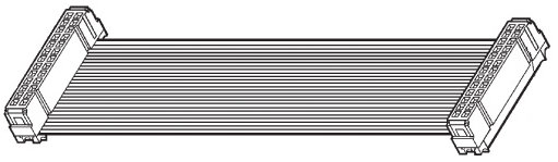
If you do want to use ribbons, IDCs (insulation-displacement connectors) are awfully convenient to mount, which is always a motivation to choose that type over other possibilities. You just put one on the ribbon and press it on with a bench vise. These are for dual-row pin headers, with .100" row spacing. Standard pin counts are 10, 14, 16, 20, 26, 34, 40, and 50, IIRC. A 26 could give you 16 address lines, 8 data, and two ground (or one ground and one virtual ground, like a power that's bypassed to ground right at the connectors). If you include R/W\, phase 2, IRQ\, etc., that would bump you up to the next standard size, 34.

Image Image


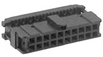
The only way I know to use wire to connect to a single-row pin header (unless you use a dual-row IDC and just don't use one row) is to crimp and/or solder individual wires to the gizmos that you then insert in a wire-applied housing. That's much more labor-intensive. The one in the poor picture below has six wires in a single row. It is connected to a programming fixture to program a microcontroller that's already soldered into the board it is used on.
Attachment:
PGMfixture5.jpg
PGMfixture5.jpg [ 54.92 KiB | Viewed 387 times ]

_________________
http://WilsonMinesCo.com/ lots of 6502 resources
The "second front page" is http://wilsonminesco.com/links.html .
What's an additional VIA among friends, anyhow?


Top
 Profile  
Reply with quote  
 Post subject: Re: Star Ground
PostPosted: Sun Nov 29, 2015 7:30 am 
Offline
User avatar

Joined: Tue Nov 16, 2010 8:00 am
Posts: 2353
Location: Gouda, The Netherlands
Another thing I always do is to put 4 mounting holes (3.2 mm hole for M3 screws) in the corners. Even if the board is just sitting on my desk, I screw in these hex spacers, so that the board is even, and the board doesn't accidentally hit tools or pieces of wire that may be lying on the desk.
Attachment:
spacer.jpg
spacer.jpg [ 2.75 KiB | Viewed 381 times ]


Top
 Profile  
Reply with quote  
 Post subject: Re: Star Ground
PostPosted: Sun Nov 29, 2015 8:50 am 
Offline
User avatar

Joined: Thu May 28, 2009 9:46 pm
Posts: 8382
Location: Midwestern USA
Arlet wrote:
Another thing I always do is to put 4 mounting holes (3.2 mm hole for M3 screws) in the corners. Even if the board is just sitting on my desk, I screw in these hex spacers, so that the board is even, and the board doesn't accidentally hit tools or pieces of wire that may be lying on the desk.

Same here. I use hex standoffs drilled and tapped for 6-32 machine screws, which screws are a smidgen larger in diameter than 3mm screws. The same type of standoffs mount the host adapter on the mainboard.

Attachment:
File comment: POC V1.1 Mounting
poc_v1_reissue_side_hba.gif
poc_v1_reissue_side_hba.gif [ 376.55 KiB | Viewed 378 times ]

_________________
x86?  We ain't got no x86.  We don't NEED no stinking x86!


Top
 Profile  
Reply with quote  
 Post subject: Re: Star Ground
PostPosted: Sun Nov 29, 2015 11:06 am 
Offline
User avatar

Joined: Sun Sep 08, 2013 10:24 am
Posts: 740
Location: A missile silo somewhere under southern England
Ok. I've added a 2x10 (20 pin) IDC for the address bus and a 2x5 (10 pin) IDC for the data bus. The bottom most 4 pins on the address bus and the bottom most 2 pins on the data bus are ground pins. I chose the number of pins as they are fairly standard and easy to get hold of. I might try making the holes that you guys are recommending, although I've not done this in eagle before. Up until now, I've been using adhesive coated rubber feet which seem to do the job.

Attachment:
newlayout2d.gif
newlayout2d.gif [ 130.33 KiB | Viewed 374 times ]


Top
 Profile  
Reply with quote  
 Post subject: Re: Star Ground
PostPosted: Sun Nov 29, 2015 11:36 am 
Offline
User avatar

Joined: Tue Nov 16, 2010 8:00 am
Posts: 2353
Location: Gouda, The Netherlands
Adding mounting holes in Eagle is simple. Go to your schematic, and click on "Add part" icon. Enter "mount-hole*" in the search bar, and hit enter. Pick the size you want. Just drop a few on the schematic, and then go to your board layout and place them where you want. Depending on your Eagle version, you could also try searching for "*hole*" and see if anything suitable pops up.

If you want your own custom hole, it's easiest to start with an existing hole, copy/paste it to your own lib, and then modify it.

Boards like these, that don't have to fit a particular case, I always make the size a multiple of 5 mm, and put the holes in the corners, 5 mm from the edges. That makes it easier if you ever want to add a base plate, or mount the board in a case.


Top
 Profile  
Reply with quote  
 Post subject: Re: Star Ground
PostPosted: Sun Nov 29, 2015 11:57 am 
Offline
User avatar

Joined: Sun Sep 08, 2013 10:24 am
Posts: 740
Location: A missile silo somewhere under southern England
Do you normally use the version with the pads?


Top
 Profile  
Reply with quote  
 Post subject: Re: Star Ground
PostPosted: Sun Nov 29, 2015 12:18 pm 
Offline
User avatar

Joined: Tue Nov 16, 2010 8:00 am
Posts: 2353
Location: Gouda, The Netherlands
I normally use non plated holes, but some of the cheaper board houses don't support those. Holes with pads are fine too, but I wouldn't connect them to anything.

If you want a convenient ground reference (for example to attach a scope clip or multimeter), I would add a test point (these are also in the eagle libraries), and insert a test pin, or a hand made loop of bare wire.


Top
 Profile  
Reply with quote  
 Post subject: Re: Star Ground
PostPosted: Sun Nov 29, 2015 2:53 pm 
Offline
User avatar

Joined: Sun Sep 08, 2013 10:24 am
Posts: 740
Location: A missile silo somewhere under southern England
Right, job done. I've managed to fit 4x 3.2mm (the 5mm ones were just way too big for the room left on my board).
My only concern is that I think I've left enough space between the edges and the holes, but what not so sure about the surrounding thru-hole components. In particular, the 2 left hand most holes and IC6 and ICs 10 and 11. Just thinking of the possibility of stess fractures between the mounting holes and the IC pin holes.

Attachment:
newlayout2e.gif
newlayout2e.gif [ 365 KiB | Viewed 369 times ]


Top
 Profile  
Reply with quote  
 Post subject: Re: Star Ground
PostPosted: Sun Nov 29, 2015 3:29 pm 
Offline
User avatar

Joined: Tue Nov 16, 2010 8:00 am
Posts: 2353
Location: Gouda, The Netherlands
I don't expect problems with fractures. The FR-4 material is very tough.

3.2mm hole is a good fit for M3 screws. That's plenty for a board like this.


Top
 Profile  
Reply with quote  
 Post subject: Re: Star Ground
PostPosted: Sun Nov 29, 2015 3:58 pm 
Offline
User avatar

Joined: Fri Aug 30, 2002 1:09 am
Posts: 8508
Location: Southern California
Yes, the material is very tough.

I hate to make you have to do things over, but note that IDCs hang off the end of the pin header a bit. They're not end-to-end stackable, which means you'll need some space between the 10-pin and the 20-pin headers. It's to accommodate the part at the ends of the IDC that holds the top clamping part down to keep the ribbon secure, and optionally a strain relief as well. This can be seen in my photo above, particularly the one of the black 20-pin polarized IDC. (Polarization is optional. It can be used in a mating shrouded pin header that has the slot in the side of the shroud so you can't plug it in backwards. Even without a shroud though, the IDC will still take more length than just the pins.)

_________________
http://WilsonMinesCo.com/ lots of 6502 resources
The "second front page" is http://wilsonminesco.com/links.html .
What's an additional VIA among friends, anyhow?


Top
 Profile  
Reply with quote  
 Post subject: Re: Star Ground
PostPosted: Sun Nov 29, 2015 5:02 pm 
Offline
User avatar

Joined: Sun Sep 08, 2013 10:24 am
Posts: 740
Location: A missile silo somewhere under southern England
This really should have occurred to me. I've now re-re-re-jigged ( :mrgreen: ) the layout so that there should (hopefully!) be enough room:

Attachment:
newlayout2f.gif
newlayout2f.gif [ 112.28 KiB | Viewed 361 times ]


Top
 Profile  
Reply with quote  
Display posts from previous:  Sort by  
Post new topic Reply to topic  [ 135 posts ]  Go to page Previous  1 ... 3, 4, 5, 6, 7, 8, 9  Next

All times are UTC


Who is online

Users browsing this forum: No registered users and 2 guests


You cannot post new topics in this forum
You cannot reply to topics in this forum
You cannot edit your posts in this forum
You cannot delete your posts in this forum
You cannot post attachments in this forum

Search for:
Jump to:  
cron