I fleshed out the design more in KiCad, and did a few PCB layouts. It's suffered quite a lot of feature-creep - it was meant to be a minimal test, but since I added in the whole I/O module, I couldn't help but make that a bit more fully-featured too. Oh well! I have an aversion to making PCBs without cramming as much as I can think of in - the idea is to make sure at least something doesn't work, as otherwise I'll just regret not being more ambitious with what I put on the PCB the first time around. We'll see, anyway.
Before sending PCBs off to manufacture, I also wanted to test the basic design on a breadboard. To do that I cloned the KiCad project and cut the complexity back a lot, including dropping the address bus to just eight bits, as that saves some ICs and a lot of wires, and is still enough to run some basic tests and probe the circuit to check the wait states are working as designed. This is the cut back schematic for the breadboard prototype:
Attachment:
File comment: CPU module
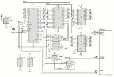 schematic-cpumodule.png [ 85.65 KiB | Viewed 28993 times ]
Attachment:
File comment: I/O+ROM module
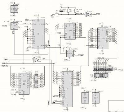 schematic-iomodule.png [ 85.59 KiB | Viewed 28993 times ]
The 8-bit address space is divided into RAM ($00-$7F), ROM ($80-$EF), I/O ($F0-$F7), and ROM again ($F8-$FF). This is just a contraction of the 16-bit address space in the main design - the PLD code is the same for both, I just wired different address lines through to it. In the 16-bit version the ROM-to-I/O cut-off is at $FF00 and the upper I/O-to-ROM boundary is at $FFC0.
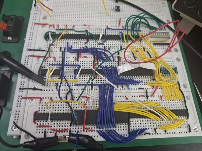
I used KiCad's PCB tool to design a sensible breadboard layout, then built it up this evening - here's the result:
Attachment:
File comment: Breadboard prototype
 breadboard.jpg [ 4 MiB | Viewed 28993 times ]
The CPU module is mostly on the bottom row, with the I/O and ROM further back. It's using a 16MHz oscillator, with a counter to divide it by up to 16. The counter is also used to generate the slower clock for the I/O module, which consequently is currently synchronous with the CPU clock - that's not the intended long term design though.
The ROM contains a couple of test programs that use the LEDs in the corner to communicate their results. One just counts up on the LEDs, the other performs RAM operations and verifies the results. I can extend this test suite fairly easily, subject to the caveat that I only have a 256-byte address space and less than half of that is ROM - still I think it's enough to make some useful test programs, and when the PCBs are done the address space limitation will be gone anyway. I use the high bits of the ROM's address inputs to select between programs, hence the long red wires.
Of course it didn't work first time - it turns out I had omitted the power connection for the CPU - but with that in place it worked perfectly well, at speeds up to 8MHz for both the CPU clock and the I/O clock. Probing some signals revealed that the slew rate on RDY was alarmingly slow:
Attachment:
File comment: Resistors on RDY cause very slow slew rates and limit clock speed
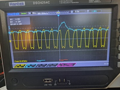 slow_rdy.jpg [ 4.05 MiB | Viewed 28993 times ]
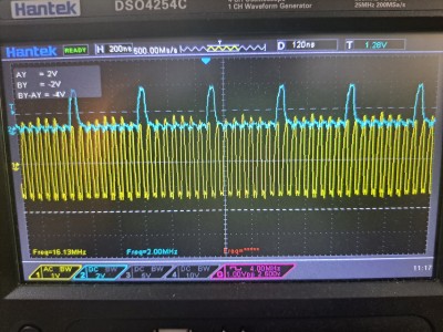
I'd used a rather large resistor there. Downgrading that to 330 ohms helped a lot - it's not a good way to hook it up though, and even a diode with a pull-up resistor doesn't feel much better. It's probably the straw that breaks the camel's back, and I should just stretch the clock instead of using RDY. Anyway, this is working well with a 16MHz clock - I also tried 25MHz as I had that oscillator handy, but it didn't work - not a huge surprise, this prototype was only meant to check the mechanisms were working, not intended to actually run at high speeds.
Attachment:
File comment: Running with a 16 MHz clock, and lots of wait states
 waitstates_16MHz.jpg [ 4.24 MiB | Viewed 28993 times ]
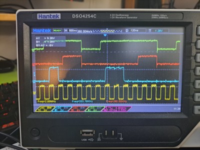
It's worth noting that the CPU isn't really running at that speed because it's constantly waiting for the I/O module. I added more probes to signals along that path to check they were behaving as expected - this shows PHI2 in yellow at the bottom, RDY in blue above it, then IOWAITS in red, and an active-low ACT signal which is where the I/O module performs the actions requested:
Attachment:
File comment: More signals - PHI2, RDY, IOWAITS, ~ACT
 phi2_rdy_iowait_act.jpg [ 4.21 MiB | Viewed 28993 times ]
So on the rising edge of PHI2, if the address has the top bit set, RDY is brought low to halt the CPU. The I/O module spots this and synchronizes the signal to its own clock, as IOWAITS, which changes in sync with the slower I/O clock. After one cycle of the I/O clock - to guard against metastability - the I/O module's ~ACT signal is brought low for one I/O clock cycle - and this controls the chip selection for any I/O devices like ROM, VIAs, and the LEDs in the corner. When that signal rises again, it causes the CPU to unpause at the next rising edge of PHI2 and continue execution.
After first I/O cycle shown in the trace above, when RDY goes high again halfway across the screen, it actually stays high for two CPU clock cycles because the next cycle is a RAM access. Then it goes low again, as the code is in ROM and it needs to fetch the next instruction.
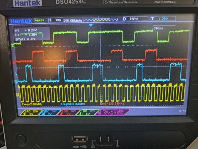
You can see that more clearly here where two instructions in a row both access RAM:
Attachment:
File comment: Two RAM access instructions in a row
 two_ram_operations.jpg [ 4.38 MiB | Viewed 28993 times ]
Here, starting with the first peak in RDY (blue), the CPU executes a slow operation from ROM (instruction fetch) so RDY goes low for a while, then high again. Then it executes another one (fetching the operand); then when RDY goes high again, the next bus operation is a RAM access and doesn't require wait states. Then after that it's back to ROM again, fetching another opcode; then an operand; then again it's able to perform a second RAM access without wait states. The instruction sequence here was STA $0 followed by CMP $0 - storing something in RAM and checking it was stored correctly.
Anyway it's working pretty well for a first pass - I'm going to write more involved RAM access tests, testing things like consecutive RAM cycles (JSR, RTS for example), and if that works, make it copy the program from ROM to RAM and run it from RAM. This should flip everything around and we should see the CPU mostly running without wait states, except when it needs to perform I/O accesses (e.g. writing to the LEDs).


