6502.org Forum  Projects  Code  Documents  Tools  Forum
It is currently Sun Jun 16, 2024 5:06 pm

All times are UTC


Post new topic Reply to topic  [ 269 posts ]  Go to page Previous  1, 2, 3, 4, 5, 6 ... 18  Next
Author Message
PostPosted: Sat Apr 27, 2013 6:56 am 
Offline
User avatar

Joined: Thu May 28, 2009 9:46 pm
Posts: 8214
Location: Midwestern USA
Dr Jefyll wrote:
The "funny" problem you describe makes me wonder about the power supply. I don't see any supply bypass capacitors -- do you have them hidden on the other side of the board? Two possible ways to proceed:

  • 'scope the supply to see if you can observe a brief sag as programming commences; or...
  • just add some capacitance and see if the symptom disappears. I'd suggest a generous electrolytic (10-100 uF maybe?) and also, located physically close to the EEPROM socket, a .1 or .01 uF with leads kept reasonably short.

Looks like a good call, Jeff. I have noted in the past that when an EPROM goes from the standby mode to active a noticeable power supply transient can occur. I quote from the AMD data sheet for their EPROMs:

    During the switch between active and standby conditions, transient current peaks are produced on the rising and falling edges of Chip Enable. The magnitude of these transient current peaks is dependent on the output capacitance loading of the device. At a minimum, a 0.1 μF ceramic capacitor (high frequency, low inherent inductance) should be used on each device between VCC and VSS to minimize transient effects. In addition, to overcome the voltage drop caused by the inductive effects of the printed circuit board traces on EPROM arrays, a 4.7 μF bulk electrolytic capacitor should be used between VCC and VSS for each eight devices. The location of the capacitor should be close to where the power supply is connected to the array.

Although AMD's data sheet is referring to EPROMs (especially an array of them), EEPROMs are behaviorly similar and could misbehave if a power supply sag occurs at the chip.

_________________
x86?  We ain't got no x86.  We don't NEED no stinking x86!


Top
 Profile  
Reply with quote  
PostPosted: Sat Apr 27, 2013 10:25 am 
Offline

Joined: Mon Mar 25, 2013 9:26 pm
Posts: 183
Location: Germany
Thanks for all the hints.
I still have problems doing a page write on the eeprom. Until now I was always trying to write the same pattern from a buffer to the eeprom. As I changed this to write different patterns (counting from 0x00 to 0x3f) it turned out, that less bytes get written correctly to the eeprom. Maybe there are more things to take care for, then I expect.

I replaced my shift-out function with a faster one, I also reduced the time to set the data lines. All settings to write data (address, data byte and /ce, /we) can be done now in 80 µs (instead of about 300 to 350 µs before). That these functions work correctly is shown by a "normal" byte write, that writes all patterns to the whole eeprom as expected. The "byte write" function also participates from the speedup of the "service functions". I can now write 8k to the eeprom wihtin 6.5 seconds. This is definitely a write cycle time I can accept. A AT28C256 can be written within 30 seconds with that speed.

So I think I will go further with my little project and start designing a PCB for it and work on the firmware that accepts data from the serial line for programming. I will take your advices and add some capacitors to the layout to take care for a proper power supply for all chips. Maybe if the final pcb version is running I will give the page write another try. The main goal is to have a cheap and easy to build programmer for EEPROMs and EPROMs that can easily be used from different systems (like USB, RS232 or even a 6522VIA) and not the best and fastest programmer ever :)

Mario.

_________________
How should I know what I think, until I hear what I've said.


Top
 Profile  
Reply with quote  
PostPosted: Sun Apr 28, 2013 3:38 pm 
Offline

Joined: Mon Mar 25, 2013 9:26 pm
Posts: 183
Location: Germany
The next small step is done. I have a small Java GUI client to that is able to talk to the programmer:

Image

At the moment I can
- load a ROM file (max. 32k) into the GUI client
- burn the first 1024 bytes of the loaded data to the EEPROM (hard coded)
- read and show the data from the EEPROM
- select the serial interface that should be used

I'm working with a fixed baud rate of 19200. There is no code to send several "chunks" of data to the programmer. So only 1024 bytes can be written from 0x0000 to 0x03ff at the moment, because it's hard coded on the GUI and also on the Arduino side. But it takes only 1.3 seconds to send and write the 1024 bytes to the eeprom. Increasing the baud rate it could be even faster (tested with 57600, it runs with 980ms). So the complete 8k of my current ROM image can be written in about 10 seconds.

Image

The second picture shows the content of the first 1024 bytes of the eeprom after writing my ROM image. All bytes are correctly written ( a lot of zeros at the moment), because all old bytes of my test data (counting from 0xff to 0x00 every 256 bytes) are replaced by the image content.

_________________
How should I know what I think, until I hear what I've said.


Top
 Profile  
Reply with quote  
PostPosted: Tue Apr 30, 2013 9:06 am 
Offline

Joined: Mon Mar 25, 2013 9:26 pm
Posts: 183
Location: Germany
Ok, after some hard fights with JAVA GUI programming and native serial communication using JAVA, I have the first working combination of Arduino-firmware and Java Client running.

Current Arduino firmware features are:

- Communication at 57600 baud
- Read content of EEPROM as hex data
- Read content of EEPROM as binary data
- Write data binary to EEPROM
- Provide "Version String" with supported commands


Current Java Client Features:

- Load ROM-Files (max 32k) into the application
- select COM-Port
- select EEPROM type (8k,16k,32k) (has influence on the number of bytes read/written)
- burn loaded ROM image to EEPROM
- load data from EEPROM binary to internal buffer
- read hex data from EEPROM (directly written to console window for testing)
- count number of different bytes between internal rom image and data on EEPROM
- clear EEPROM with 0x00
- get the Version Sting from the MEEPROMMER

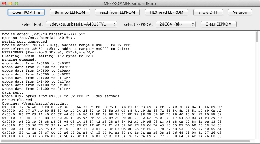
Here's a short collection of screenshots from the GUI:

GUI after start, selecting different EEPROM types, getting Version String, clearing EEPROM and loading a 8k ROM image:
Image

GUI after making a diff between the cleared EEPROM and the loaded 8k ROM image, showing all 8192 bytes as different:
Image

GUI after writing the ROM image to the EEPROM and then making a diff again.
Image

Now showing that all bytes are equal:
Image


I found one additional issue with the EEPROMs I'm using for my tests.
I have 5 Atmel "AT28C64-15PC (0828)". I tested two of them and I can write the 8k in about 8 seconds, using /DATA polling to get the end of a write cycle.

I have one Atmel "AT28C64B-15PU (1212)" that takes about 6 times longer to write. It took 47 seconds to clear the chip, or to write data to it. This was the chip I used initially for my first tests.

For reading there is no difference between these chips. I can read the whole 8k of the chip within 1.4 seconds with my Programmer and the Java tool.

Does anybody know about such big differences in write-times for these kind of EEPROM?

_________________
How should I know what I think, until I hear what I've said.


Top
 Profile  
Reply with quote  
PostPosted: Tue Apr 30, 2013 10:10 pm 
Offline

Joined: Mon Jan 07, 2013 2:42 pm
Posts: 576
Location: Just outside Berlin, Germany
So I've finished building a bed and a matching night stand, turned our veggie gardens, broke ground for a new plot of said garden, spent three afternoons digging another plot only to find out that there is some sort of foundation underneath and then filled it all up again, harvested the compost heap (new record of 180 liters), rebuilt the compost heap, and planted veggies for this year. Now finally I found some time to get back to computers.

Great work, Mario! I'll be (finally) trying to build my own hardware in May, I actually should have a whole week off end of the month. In the meantime, I have managed to become more familiar with the Python argparse module and have re-written the interface so that the help strings and input testing are handled automatically. You can pretty much type in all the commands and options in this version, though it of course won't actually do anything yet. But getting there, and soon to include radishes.


Attachments:
meepromer.txt [6.85 KiB]
Downloaded 287 times
Top
 Profile  
Reply with quote  
PostPosted: Fri May 10, 2013 10:01 pm 
Offline
User avatar

Joined: Tue Mar 02, 2004 8:55 am
Posts: 996
Location: Berkshire, UK
I've not played with EEPROM devices since my first job so I thought I'd go but using my customary PIC chip so I knocked up this big mess of wires.
Attachment:
File comment: PIC EEPROM Programmer
IMG_0679.JPG
IMG_0679.JPG [ 3.1 MiB | Viewed 9731 times ]

It's just a 18F4620 with three 100nF decoupling capacitors. I'm using a PL2303 based USB CDC module to power the board and connect to a PC.

I'm going to knock up a little adapter to allow me to convert an AT28C64 to a 27C32 socket so I can use it to finish writing and testing the firmware for my R6501 SBC.

_________________
Andrew Jacobs
6502 & PIC Stuff - http://www.obelisk.me.uk/
Cross-Platform 6502/65C02/65816 Macro Assembler - http://www.obelisk.me.uk/dev65/
Open Source Projects - https://github.com/andrew-jacobs


Top
 Profile  
Reply with quote  
PostPosted: Sat May 11, 2013 5:12 pm 
Offline

Joined: Sun Nov 01, 2009 2:22 pm
Posts: 21
Location: United Kingdom
Is there any merit in modifying this circuit so that it's all built on a board that includes the nano board itself, enough Ram and a DIP plug that could plug directly into the project ROM socket?

It seems to me such an arrangement would remove the need to run through the; pull (EEP)ROM, erase, program, plug (EEP)ROM back in cycle. Simply downloading the new code image to RAM and switching the ram into the project board ROM space, hand over to the project processor once the download has completed.

I came across this via hackaday http://fourwalledcubicle.com/blog/2013/03/the-new-lufa-bootloader/ the principle could be adapted to use a parallel port, implemented say with a 6522 in the target. In which case you would just need a plug in daughter board with ROM using the host 65x processor to download into shadow RAM on the daughter board - switch out the ROM and trigger the target reset to run the downloaded program from the shadow RAM.

One board would be good for any project ( so long as it had a parallel capability ).


Top
 Profile  
Reply with quote  
PostPosted: Mon May 13, 2013 6:12 am 
Offline

Joined: Mon Mar 25, 2013 9:26 pm
Posts: 183
Location: Germany
The MEEPROMMER got his own site now. Only in german at the moment, but I will change this after my holidays.
http://www.ichbinzustaendig.de/dev/meeprommer

_________________
How should I know what I think, until I hear what I've said.


Top
 Profile  
Reply with quote  
PostPosted: Tue May 28, 2013 2:10 am 
Offline

Joined: Tue May 28, 2013 1:42 am
Posts: 32
Boy is it hard to create an account on this forum.. heh, I found this thread while doing some google searching.
Mario, your work is awesome. I used the schematic you posted to create a shield for a standard Arduino, as I have a bunch of those, and the Nano is obsolete (replaced by the Micro).
Image
Thanks for all the hard work on this. You should really post this in the Arduino forum. I'm going to be using this to program EEPROMs for my cars.


Top
 Profile  
Reply with quote  
PostPosted: Sun Jun 02, 2013 12:14 am 
Offline
User avatar

Joined: Wed Feb 13, 2013 1:38 pm
Posts: 587
Location: Michigan, USA
BitWise wrote:
I've not played with EEPROM devices since my first job so I thought I'd go but using my customary PIC chip so I knocked up this big mess of wires.

It's just a 18F4620 with three 100nF decoupling capacitors. I'm using a PL2303 based USB CDC module to power the board and connect to a PC.

I'm going to knock up a little adapter to allow me to convert an AT28C64 to a 27C32 socket so I can use it to finish writing and testing the firmware for my R6501 SBC.


Andrew (BitWise):

It occurs to me that I could duplicate your approach and implement a 12.5v VPP boost circuit, like that on the PICKIT2, and replace my old 68HC11 EPROM/EEPROM burner (27C64, 27C128, 27C256, and 28C256 devices) with a Windows version that runs on a single 5v supply. What do you think?

Cheerful regards, Mike

Attachment:
EPROM Programmer Pwr Switching.png
EPROM Programmer Pwr Switching.png [ 626.86 KiB | Viewed 9623 times ]


Top
 Profile  
Reply with quote  
PostPosted: Sun Jun 02, 2013 11:11 am 
Offline
User avatar

Joined: Tue Mar 02, 2004 8:55 am
Posts: 996
Location: Berkshire, UK
Michael wrote:
BitWise wrote:
I've not played with EEPROM devices since my first job so I thought I'd go but using my customary PIC chip so I knocked up this big mess of wires.

It's just a 18F4620 with three 100nF decoupling capacitors. I'm using a PL2303 based USB CDC module to power the board and connect to a PC.

I'm going to knock up a little adapter to allow me to convert an AT28C64 to a 27C32 socket so I can use it to finish writing and testing the firmware for my R6501 SBC.


Andrew (BitWise):

It occurs to me that I could duplicate your approach and implement a 12.5v VPP boost circuit, like that on the PICKIT2, and replace my old 68HC11 EPROM/EEPROM burner (27C64, 27C128, 27C256, and 28C256 devices) with a Windows version that runs on a single 5v supply. What do you think?

Cheerful regards, Mike

Attachment:
The attachment EPROM Programmer Pwr Switching.png is no longer available


Sounds plausible to me but I'm more software than hardware. I've attached my circuit and code. Feel free to use and abuse.


Attachments:
File comment: The code
EP-28CXXX (18F4620).zip [29.32 KiB]
Downloaded 581 times
File comment: Schematic
Schematic.png
Schematic.png [ 20.56 KiB | Viewed 9609 times ]

_________________
Andrew Jacobs
6502 & PIC Stuff - http://www.obelisk.me.uk/
Cross-Platform 6502/65C02/65816 Macro Assembler - http://www.obelisk.me.uk/dev65/
Open Source Projects - https://github.com/andrew-jacobs
Top
 Profile  
Reply with quote  
PostPosted: Fri Jun 21, 2013 1:10 am 
Offline

Joined: Tue May 28, 2013 1:42 am
Posts: 32
Got my shields made. Ended up cutting the size of the shields down to get it under the 5cmx5cm limit at SeeedStudio, to keep the price low. I'll test it out this weekend and see if I got it right. If anyone wants the EagleCAD files, let me know, I'd be happy to share.
Image


Top
 Profile  
Reply with quote  
PostPosted: Fri Jun 21, 2013 9:05 am 
Offline
User avatar

Joined: Thu Dec 11, 2008 1:28 pm
Posts: 10828
Location: England
Nice!


Top
 Profile  
Reply with quote  
PostPosted: Fri Jun 21, 2013 2:00 pm 
Offline

Joined: Mon Mar 25, 2013 9:26 pm
Posts: 183
Location: Germany
Really cool. Thanks for your effort. Can you post the Eagle files here? I would like to include them in my MEEPROMMER page. Maybe thre is enough room for a ZIF socket instead of the normal IC socket.

_________________
How should I know what I think, until I hear what I've said.


Top
 Profile  
Reply with quote  
PostPosted: Fri Jun 21, 2013 4:05 pm 
Offline

Joined: Tue May 28, 2013 1:42 am
Posts: 32
Yeah, there should be plenty of room there for a ZIF socket, I just used what I had laying around when I assembled it. Attached are my eagle files, as well as the gerbers I submitted to have the boards made.
After I confirm this thing works, I'll toss the extras up on Tindie.com for a very low price in case anyone wants to just get one of these that I made.


Attachments:
File comment: EagleCAD files, as well as gerbers.
eeprom_burner.zip [59.33 KiB]
Downloaded 642 times
Top
 Profile  
Reply with quote  
Display posts from previous:  Sort by  
Post new topic Reply to topic  [ 269 posts ]  Go to page Previous  1, 2, 3, 4, 5, 6 ... 18  Next

All times are UTC


Who is online

Users browsing this forum: No registered users and 37 guests


You cannot post new topics in this forum
You cannot reply to topics in this forum
You cannot edit your posts in this forum
You cannot delete your posts in this forum
You cannot post attachments in this forum

Search for:
Jump to: