You have a french Fan!
Be sure that i will follow your trip and translate your stuff in french for growing the community.
Vulcan-74 - A 6502 Powered Retro MegaProject
-
Oneironaut

- Posts: 734
- Joined: 25 May 2015
- Location: Gillies, Ontario, Canada
- Contact:
Re: Vulcan-74 - A 6502 Retro MegaProject
Thanks again to everyone for the positive feedback on this project!
I never would have imagined that this thread would have even 1000 views!
I have made the last needed alterations to allow the 6502 to move into its new home.
All IO are 6502 compatible now, and the multiplexing system works as planned.
It was a bit of a challenge moving the IO from the freedom of AVR to the constraints of 6502, but it's all done now.
I had to add 4 more ICs to the board, mainly to isolate the Sprite & playfiled databus form the 6502 while they run.
Vulcan-74 now has 3 fully independent, yet bridgeable busses, each having 20 bit addressing and 8 bit data.
I also took this afternoon to hack out the other aluminum panel that will make the second massive breadboard for the sound processor.
The back panel will be drilled soon, giving Vulcan a few new ports; Audio (1/8" Stereo jack), and dual Joystick (9 pin C64 / Atari style).
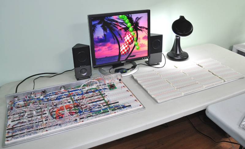
Size matters when you prototype with 250 ICs!
Realizing that my computer desk was now too small to fit the dual board, I added another desk to my basement lab to make room!
Zoinks Scoob!... when placed side by side, the new Mega Breadboard is 56 inches by 15 inches in size (almost 6 square feet)!
Perhaps Guinness would put this one down as "The World's Largest Solderless Breadboard"? ..always fun to get in the record book!
Over the next bursts of free time, I plan on dropping in the 6502 and boot-loader so I can begin the IO testing under complete 6502 control.
Things are really starting to progress!
Later,
Radical Brad
I never would have imagined that this thread would have even 1000 views!
I have made the last needed alterations to allow the 6502 to move into its new home.
All IO are 6502 compatible now, and the multiplexing system works as planned.
It was a bit of a challenge moving the IO from the freedom of AVR to the constraints of 6502, but it's all done now.
I had to add 4 more ICs to the board, mainly to isolate the Sprite & playfiled databus form the 6502 while they run.
Vulcan-74 now has 3 fully independent, yet bridgeable busses, each having 20 bit addressing and 8 bit data.
I also took this afternoon to hack out the other aluminum panel that will make the second massive breadboard for the sound processor.
The back panel will be drilled soon, giving Vulcan a few new ports; Audio (1/8" Stereo jack), and dual Joystick (9 pin C64 / Atari style).
Size matters when you prototype with 250 ICs!
Realizing that my computer desk was now too small to fit the dual board, I added another desk to my basement lab to make room!
Zoinks Scoob!... when placed side by side, the new Mega Breadboard is 56 inches by 15 inches in size (almost 6 square feet)!
Perhaps Guinness would put this one down as "The World's Largest Solderless Breadboard"? ..always fun to get in the record book!
Over the next bursts of free time, I plan on dropping in the 6502 and boot-loader so I can begin the IO testing under complete 6502 control.
Things are really starting to progress!
Later,
Radical Brad
-
ElEctric_EyE
- Posts: 3260
- Joined: 02 Mar 2009
- Location: OH, USA
Re: Vulcan-74 - A 6502 Retro MegaProject
You sir have redefined "hi-speed" on 2 levels.
1) ~15MHz clean video on breadboard with discrete TTL
2) the speed at which you progress is also admirable, due to cheap parts especially
Looking forward to your sound board too. What kind of features are you looking to put into it?
1) ~15MHz clean video on breadboard with discrete TTL
2) the speed at which you progress is also admirable, due to cheap parts especially
Looking forward to your sound board too. What kind of features are you looking to put into it?
-
Oneironaut
- Posts: 734
- Joined: 25 May 2015
- Location: Gillies, Ontario, Canada
- Contact:
Re: Vulcan-74 - A 6502 Retro MegaProject
Thanks!
Progress has been ok, but I wish I had more than a few hours on the weekend to work on this project.
It's getting frosty out these days, so I may find more indoor time soon.
I now have the entire board running from two different clocks...
20MHz : VGA System and Sprite Generator.
32MHz : Playfield Generator, and 6502 (will be divided to 16MHz).
Because the Sound Generator will only require a slow clock, I will probably just divide the 32MHz clock by 4 or 8 to drive it.
Here is my "Required" Sound Generator features list....
- 4 independent 8 bit digital sound sample voices, mixed down into 2 Stereo Channels.
- Each voice will have 16 bit frequency control, 8 bit volume control, and an 8 bit low pass filter control.
- Sound Memory is also 1024K, and each Voice can set a sample anywhere in the memory.
- A Sound Sample ends when a value of 255 is read. There are no limits to the number of stored samples in memory.
- Samples can be set to play once or loop continuously.
- The entire Sound Generator will require 4x9=36 IO lines, and will run as an independent system.
Work on the Sound Generator will begin once the 6502 is controlling the board.
If time permits, the 6502 could be installed and self aware this weekend.
Cheers!
Radical Brad
ElEctric_EyE wrote:
You sir have redefined "hi-speed" on 2 levels.
1) ~15MHz clean video on breadboard with discrete TTL
2) he speed at which you progress is also admirable, due to cheap parts especially
Looking forward to your sound board too. What kind of features are you looking to put into it?
1) ~15MHz clean video on breadboard with discrete TTL
2) he speed at which you progress is also admirable, due to cheap parts especially
Looking forward to your sound board too. What kind of features are you looking to put into it?
Last edited by Oneironaut on Thu Oct 08, 2015 2:04 pm, edited 1 time in total.
Re: Vulcan-74 - A 6502 Retro MegaProject
You should take a look at the variable sample rate playback system used in the classic PPG synths of the 80s. There when a sample from a wavetable is played back the actual clock frequency at which the data is read from memory (and sent direct to DAC) is adjusted relative to the frequency rather than having a fixed sample rate (say 44khz) and interpolating or dropping bytes from the sample data to match. This leads to markedly less aliasing, it's quite novel. Here's a discussion here: http://electricdruid.net/wavetable-oscillators/
-
Oneironaut
- Posts: 734
- Joined: 25 May 2015
- Location: Gillies, Ontario, Canada
- Contact:
Re: Vulcan-74 - A 6502 Retro MegaProject
Thanks for the info.
Unlike a DDS, in my design, the clock that drives the memory counters is adjusted, so there will be no dropped bytes.
Each Voice has its own fully independent 20 bit counter, which is driven by another independent counter that is wrapped by a 16 bit value stored in a set of 74HC688 comparators.
So if the "Master" sound clock is 10MHz, each channel counter can be set from 152Hz to 5MHz with 16 bit precision.
I tested something similar using only 8 bit precision a few years back, but the frequencies were not close enough to span many octaves.
Playback frequency will depend on the original sampling rate of the stored data.
Brad
porcupine wrote:
You should take a look at the variable sample rate playback system used in the classic PPG synths of the 80s. There when a sample from a wavetable is played back the actual clock frequency at which the data is read from memory (and sent direct to DAC) is adjusted relative to the frequency rather than having a fixed sample rate (say 44khz) and interpolating or dropping bytes from the sample data to match. This leads to markedly less aliasing, it's quite novel. Here's a discussion here: http://electricdruid.net/wavetable-oscillators/
Last edited by Oneironaut on Thu Oct 08, 2015 2:44 am, edited 1 time in total.
Re: Vulcan-74 - A 6502 Retro MegaProject
Ok cool, that's the same design as the PPG oscillators I linked to.
Again, nice work!
Again, nice work!
Oneironaut wrote:
Unlike a DDS, in my design, the clock that drives the memory counters is adjusted, so there will be no dropped bytes.
Each Voice has its own fully independent 20 bit counter, which is driven by another independent counter that is wrapped by a 16 bit value stored in a set of 74HC688 comparators.
Brad
Each Voice has its own fully independent 20 bit counter, which is driven by another independent counter that is wrapped by a 16 bit value stored in a set of 74HC688 comparators.
Brad
porcupine wrote:
You should take a look at the variable sample rate playback system used in the classic PPG synths of the 80s. There when a sample from a wavetable is played back the actual clock frequency at which the data is read from memory (and sent direct to DAC) is adjusted relative to the frequency rather than having a fixed sample rate (say 44khz) and interpolating or dropping bytes from the sample data to match. This leads to markedly less aliasing, it's quite novel. Here's a discussion here: http://electricdruid.net/wavetable-oscillators/
-
Oneironaut
- Posts: 734
- Joined: 25 May 2015
- Location: Gillies, Ontario, Canada
- Contact:
Re: Vulcan-74 - A 6502 Retro MegaProject
Thanks.
On another "note", having been into music since the big-hair 80's years, I agree with the way they re-sample instruments for each octave.
When I did any kind of piano mixing in OctaMed (Amiga tracker), I used to record individual octaves or even single key strikes this way.
With a piano, simply speeding up or slowing down the sample playback to match a certain frequency will ruin the sound of the instrument, as the envelope changes and small nuances such as the mechanical sounds are adjusted. In a "thick" song with a lot going on, it's not as noticeable, but when a guitar or piano is the focus, you can really notice it. A good example is the piano intro music for the Amiga game "Agony". If I remember, they sampled every single note.
https://www.youtube.com/watch?v=X9UTnUcyED0
For the day, this sounded pretty damn good!
Good thing I have a meg of RAM to use in my Sound Generator!
Oh, and the new breadboard is done... will post photos tonight.
Brad
porcupine wrote:
Ok cool, that's the same design as the PPG oscillators I linked to.
Again, nice work!
Again, nice work!
Oneironaut wrote:
Unlike a DDS, in my design, the clock that drives the memory counters is adjusted, so there will be no dropped bytes.
Each Voice has its own fully independent 20 bit counter, which is driven by another independent counter that is wrapped by a 16 bit value stored in a set of 74HC688 comparators.
Brad
Each Voice has its own fully independent 20 bit counter, which is driven by another independent counter that is wrapped by a 16 bit value stored in a set of 74HC688 comparators.
Brad
porcupine wrote:
You should take a look at the variable sample rate playback system used in the classic PPG synths of the 80s. There when a sample from a wavetable is played back the actual clock frequency at which the data is read from memory (and sent direct to DAC) is adjusted relative to the frequency rather than having a fixed sample rate (say 44khz) and interpolating or dropping bytes from the sample data to match. This leads to markedly less aliasing, it's quite novel. Here's a discussion here: http://electricdruid.net/wavetable-oscillators/
-
Oneironaut
- Posts: 734
- Joined: 25 May 2015
- Location: Gillies, Ontario, Canada
- Contact:
Re: Vulcan-74 - A 6502 Retro MegaProject
The Vulcan-74 breadboard has now doubled in size!
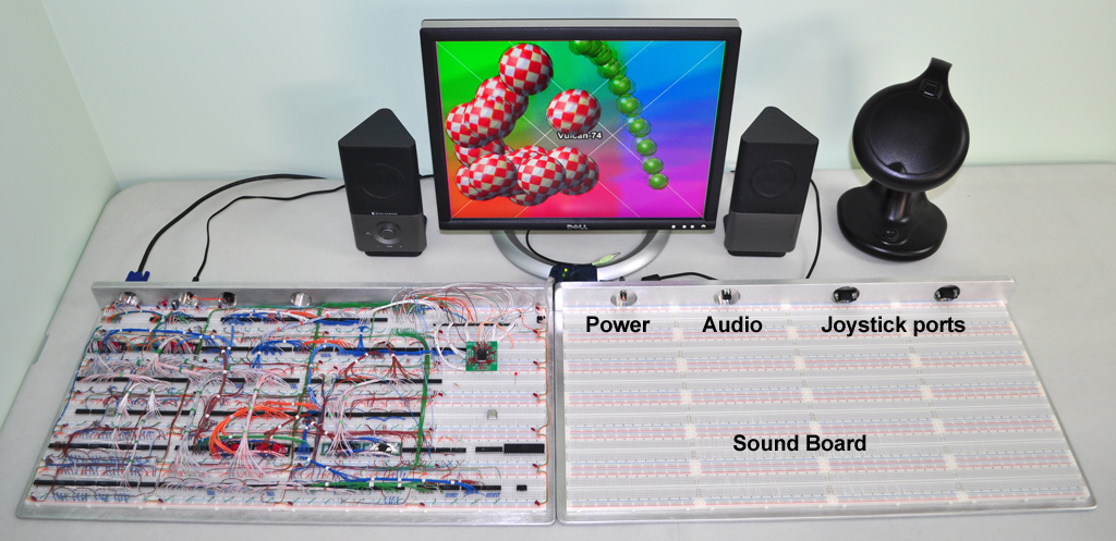
The second board will contain the Sound Processor.
Because I ran out of room on what I thought would be a "large enough" board, I went and made another monster breadboard.
The new board will (hopefully) fit all of the ICs needed for the Sound Processor, and a the 6502 Boot System.
I may only be able to get 2 of the 4 channels installed, but that would be good enough, since they are all identical.
Who would ever need more than 48 breadboards???
... The same kind of freaks that need more than 640K!
Anyhow, I will be putting in the 6502 on my next free day.
Not sure about this weekend though... still have 5 cords of wood to cut and split, and its getting below zero at night out here!
Later!
Radical Brad
Last edited by Oneironaut on Tue Oct 13, 2015 9:07 pm, edited 1 time in total.
-
Oneironaut
- Posts: 734
- Joined: 25 May 2015
- Location: Gillies, Ontario, Canada
- Contact:
Re: Vulcan-74 - A 6502 Retro MegaProject
A rainy day has given me some real time in my lab to rework the entire IO System so that it will be 6502 compatible.
Here is what was done today...
- Remove the XMega that was controlling all 30 individual IO Lines and the Address Bus.
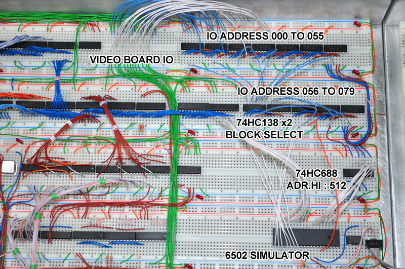
- Add multiplexers to control up to 80 IO lines through 8 bit addressing (74HC138s).
- Add a 74HC688 comparator to detect the Hi Address value of 512 (6502 IO Page).
- Add 6502 style clock control to the multiplexer to only toggle IO during the Clock Hi Phase.
- Recode my entire XMega code to AVR ATmega to simulate the 6502 Address and Data Bus.
- Test the new IO System using the AVR 6502 Simulator code.
The IO System is now 6502 Compatible!
The AVR 6502 Simulator address the Vulcan IO System just like the 6502 will, using a 16 bit Address Bus, 8 bit Data Bus, and RW Line.
Just like the 6502, the AVR only assumes valid data send or read from the bus during the clock high cycle.
I will be basing my 6502 libraries on the AVR assembly libraries written here, as the assembly syntax is so similar.
At this point, RW is not simulated because there is no external program memory (64K SRAM) on the 6502 bus.
Because of the way the IO System functions, RW will only have the job of disabling the SRAM during mapped IO reads.
I placed my 80 bit mapped IO lines at address 512 to 592. 80 IO lines will be plenty to control all Video and Sound functions.
As usual, 000 to 255 will be Page Zero, and 256 to 511 will be hardware stack. Everything beyond 767 is program memory.
As soon as I tighten up the AVR assembly libraries, I am dropping in the 6502!!!
The AVR will remain ONLY to boot load the 64K program memory for the 6502 until my boot logic is completed.
So far, everything is working exactly as planned!
Cheers!
Radical Brad
Here is what was done today...
- Remove the XMega that was controlling all 30 individual IO Lines and the Address Bus.
- Add multiplexers to control up to 80 IO lines through 8 bit addressing (74HC138s).
- Add a 74HC688 comparator to detect the Hi Address value of 512 (6502 IO Page).
- Add 6502 style clock control to the multiplexer to only toggle IO during the Clock Hi Phase.
- Recode my entire XMega code to AVR ATmega to simulate the 6502 Address and Data Bus.
- Test the new IO System using the AVR 6502 Simulator code.
The IO System is now 6502 Compatible!
The AVR 6502 Simulator address the Vulcan IO System just like the 6502 will, using a 16 bit Address Bus, 8 bit Data Bus, and RW Line.
Just like the 6502, the AVR only assumes valid data send or read from the bus during the clock high cycle.
I will be basing my 6502 libraries on the AVR assembly libraries written here, as the assembly syntax is so similar.
At this point, RW is not simulated because there is no external program memory (64K SRAM) on the 6502 bus.
Because of the way the IO System functions, RW will only have the job of disabling the SRAM during mapped IO reads.
I placed my 80 bit mapped IO lines at address 512 to 592. 80 IO lines will be plenty to control all Video and Sound functions.
As usual, 000 to 255 will be Page Zero, and 256 to 511 will be hardware stack. Everything beyond 767 is program memory.
As soon as I tighten up the AVR assembly libraries, I am dropping in the 6502!!!
The AVR will remain ONLY to boot load the 64K program memory for the 6502 until my boot logic is completed.
So far, everything is working exactly as planned!
Cheers!
Radical Brad
Re: Vulcan-74 - A 6502 Retro MegaProject
Your wiring is a thing of beauty. I assume you're planning on putting the breadboards themselves into a display case and not one or more giant PC boards which would be much less impressive, IMHO?
Your plans remind me of this "tapestry" the late Jim Williams had on his living room wall: http://m.eet.com/media/1102446/minuteman02.gif
BTW, I thought you said you get all of your wires from ethernet cable and I've been meaning to ask you: I cut open some CAT5e and CAT6 I had laying around and they were both filled with stranded wires. Can you still pick up bulk cable with solid copper wires inside cheaply somewhere?
-
BigDumbDinosaur

- Posts: 9428
- Joined: 28 May 2009
- Location: Midwestern USA (JB Pritzker’s dystopia)
- Contact:
Re: Vulcan-74 - A 6502 Retro MegaProject
jmp(FFFA) wrote:
BTW, I thought you said you get all of your wires from ethernet cable and I've been meaning to ask you: I cut open some CAT5e and CAT6 I had laying around and they were both filled with stranded wires. Can you still pick up bulk cable with solid copper wires inside cheaply somewhere?
x86? We ain't got no x86. We don't NEED no stinking x86!
-
Oneironaut
- Posts: 734
- Joined: 25 May 2015
- Location: Gillies, Ontario, Canada
- Contact:
Re: Vulcan-74 - A 6502 Retro MegaProject
Thanks again!
Yes, bulk network wiring is almost always solid copper. A 1000 foot box can wire a copious number of breadboards!
Added a quick video of the 6502 simulator doing some basic IO testing at 20MHz...
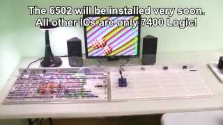
https://www.youtube.com/watch?v=CxonyIrZhDc
Sorry for the quality of the screenshot... the camera bloomed all to hell since the room lighting was dim.
Also, there is no jitter or tearing in the live video. Unlike the Youtube encode, the real deal is perfect in every way!
I will not accept even a single pixel out of place... not one!
Oh, and just to mention (rant) the reason I call it "Address location 512-767" rather than "200-2FF" is due to the fact that I am still mostly human, and until someone removes the last working section of my grey matter and jams in a CPU, I refuse to speak in HEX! There is no point to that silliness, and I will have no part of it dude! In my twisted world, the damn 6502 reset vector address is at locations 65532-65533, not FFFC-FFFC! Ok, just had to get that out!
Next report will show the 6502 controlling the board!
...later!
Radical Brad
Yes, bulk network wiring is almost always solid copper. A 1000 foot box can wire a copious number of breadboards!
Added a quick video of the 6502 simulator doing some basic IO testing at 20MHz...
https://www.youtube.com/watch?v=CxonyIrZhDc
Sorry for the quality of the screenshot... the camera bloomed all to hell since the room lighting was dim.
Also, there is no jitter or tearing in the live video. Unlike the Youtube encode, the real deal is perfect in every way!
I will not accept even a single pixel out of place... not one!
Oh, and just to mention (rant) the reason I call it "Address location 512-767" rather than "200-2FF" is due to the fact that I am still mostly human, and until someone removes the last working section of my grey matter and jams in a CPU, I refuse to speak in HEX! There is no point to that silliness, and I will have no part of it dude! In my twisted world, the damn 6502 reset vector address is at locations 65532-65533, not FFFC-FFFC! Ok, just had to get that out!
Next report will show the 6502 controlling the board!
...later!
Radical Brad
-
Oneironaut
- Posts: 734
- Joined: 25 May 2015
- Location: Gillies, Ontario, Canada
- Contact:
Re: Vulcan-74 - A 6502 Retro MegaProject
Look who came to the party!...
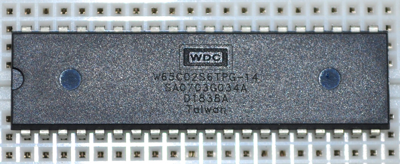
Now the real fun begins, as I have never used a 6502 beyond a basic RW test.
I am starting with a slow 4MHz clock and a 15ns 32K SRAM until I wire up another 10ns SRAM.
Initial testing will involve pre-loading the SRAM via AVR and then letting Mr. Peddle take the helm.
Will report back next time I have an hour to get it all wired up for a smoke test!
Radical Brad
-
ElEctric_EyE
- Posts: 3260
- Joined: 02 Mar 2009
- Location: OH, USA
Re: Vulcan-74 - A 6502 Retro MegaProject
When you start writing 6502 ML code you WILL eventually embrace the HEX. Resistance is futile!