6502.org Forum  Projects  Code  Documents  Tools  Forum
It is currently Sun Nov 24, 2024 6:59 am

All times are UTC


Post new topic Reply to topic  [ 49 posts ]  Go to page Previous  1, 2, 3, 4
Author Message
PostPosted: Tue Sep 11, 2018 9:37 am 
Offline

Joined: Wed Oct 06, 2010 9:05 am
Posts: 95
Location: Palma, Spain
hoglet wrote:
- the minimum interrupt latency is only one clock cycle (elsewhere I'd seen this stated as two clock cycles)

How are you getting one clock cycle latency?

Here's the lowest latency I can get out of Visual 6502:
http://visual6502.org/JSSim/expert.html ... nc,irq,480

IRQ fired at the end of cycle 6, interrupt sequence starts on cycle 8 (or really on cycle 9, because cycle 8 is just the opcode fetch and discard). The three consecutive stack writes don't even happen until cycle 10!


Top
 Profile  
Reply with quote  
PostPosted: Tue Sep 11, 2018 10:23 am 
Offline

Joined: Sun Jun 29, 2014 5:42 am
Posts: 352
Hi Rich,
RichTW wrote:
How are you getting one clock cycle latency?

I've probably confused things slightly by talking about interrupt latency as the time from the falling edge of NMI/IRQ to the start of the 7-cycle interrupt sequence. The minimum interrupt latency, including the 7-cycle interrupt sequence, is actually 8 cycles.

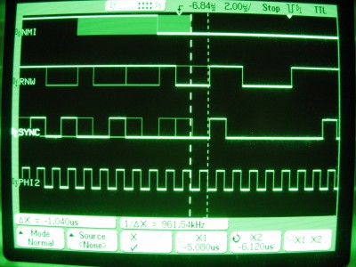
You can directly read the minimum latency off the scope plots (which accumulated many measurements over about a minute). The NMI trace shows all shows all possible points at which NMI was seen to fall prior to the trigger event, which was the interrupt sequence (specifically the 3 cycle write):
Attachment:
IMG_1440.JPG
IMG_1440.JPG [ 418.51 KiB | Viewed 3848 times ]

The left cursor marks the latest point where NMI was seen to fall, just prior to the interrupt sequence starting. The right cursor marks the Phi2 edge just prior to sync going hi. The difference between these cursors is 1.040us, so a tad over one clock cycle. The trace for IRQ looks pretty much identical.

Your Visual6502 example is interesting, in that it shows 1.5 cycles between IRQ going low and the sync at the start of the 7-cycle interrupt sequence. That's a difference of half a cycle compared to what I see in reality. I guess the explanation is that Visual6502 is only working in whole half cycles, and 1.0 cycles is just too late.

Dave


Top
 Profile  
Reply with quote  
PostPosted: Tue Sep 11, 2018 11:40 am 
Offline

Joined: Wed Oct 06, 2010 9:05 am
Posts: 95
Location: Palma, Spain
Yes, that makes sense. I'm not sure what internal model Visual6502 uses, but I guess certain quantisation issues will give different results when the timing is as fine as this.

Still, interesting to see some operational differences between NMOS and CMOS variants, and not just instruction set related things. I guess the ADC/SBC instructions in binary mode (which skip the extra cycle at the end for decimal mode flag fixup) would have the same 'problem' (T0 skipped) so maybe it was necessary to find a better solution for this issue.


Top
 Profile  
Reply with quote  
PostPosted: Tue Sep 11, 2018 4:20 pm 
Offline
User avatar

Joined: Thu Dec 11, 2008 1:28 pm
Posts: 10986
Location: England
Yes, sounds like 1+ε is the latency when measured this way, and on visual6502 that looks like 1.5


Top
 Profile  
Reply with quote  
Display posts from previous:  Sort by  
Post new topic Reply to topic  [ 49 posts ]  Go to page Previous  1, 2, 3, 4

All times are UTC


Who is online

Users browsing this forum: No registered users and 55 guests


You cannot post new topics in this forum
You cannot reply to topics in this forum
You cannot edit your posts in this forum
You cannot delete your posts in this forum
You cannot post attachments in this forum

Search for:
Jump to: