6502.org Forum  Projects  Code  Documents  Tools  Forum
It is currently Sun Jul 07, 2024 2:31 pm

All times are UTC


Post new topic Reply to topic  [ 733 posts ]  Go to page Previous  1 ... 5, 6, 7, 8, 9, 10, 11 ... 49  Next
Author Message
PostPosted: Thu Aug 13, 2015 12:00 pm 
Offline
User avatar

Joined: Mon May 25, 2015 2:25 pm
Posts: 632
Location: Gillies, Ontario, Canada
It really depends on how you read the "official" definitions of both as shown here...

https://en.wikipedia.org/wiki/Blitter

Because the logic in what I call the Sprite Processor is not available as standard memory to the CPU and because it can only be used to lay down graphics to the inactive back buffer by issuing commands, it could be called a sprite engine. It does not work line by line because it has full X and Y processing. The logic cannot be used to move one line of memory to another, it can only draw bitmaps (with one ignored color value) to the back buffer.

Image
All Graphics are drawn by the logic, directly to the Back Buffer. The CPU is not halted.

I originally designed collision detection, but this was severely limiting, since "Sprites" would then have to either be defined by fixed size, or the logic would have to do a read of the back buffer before writing each pixel. On a 200x200 sized sprite, this would be a lot of memory reading and comparing!

So in reality, I think my logic is closer to a "Sprite Engine" then a "Blitter", just because it does only one thing... moves defined bitmaps to the back buffer with one transparent pixel without holding back the CPU.

But rather then jumping in on the growing debate on Hackaday, I decided to keep the name "Sprite Generator" regardless.
After all, I was never one to follow rules and recommendations and trends. If I did, I would have never started building this thing!

Maybe I should rename it to "Spritter Engine"!

Brad


BigEd wrote:
To clarify a question raised on Hackaday - could you confirm that there are no sprite engines here, but there is a blitter, so the sprites you demonstrate would by some people be called Blitter Objects.

(In the case of a sprite engine, there'd be limits on sprite numbers, and there might be sprite collision detection in hardware.)


Top
 Profile  
Reply with quote  
PostPosted: Thu Aug 13, 2015 12:19 pm 
Offline
User avatar

Joined: Thu Dec 11, 2008 1:28 pm
Posts: 10838
Location: England
Great photo! I'm not too worried about the terminology myself. Perhaps for me a sprite engine gets graphics to the screen without drawing or undrawing into a full screen bitmap.


Top
 Profile  
Reply with quote  
PostPosted: Thu Aug 13, 2015 12:33 pm 
Offline
User avatar

Joined: Mon May 25, 2015 2:25 pm
Posts: 632
Location: Gillies, Ontario, Canada
Agreed on that point, but here is a "workaround"...

Since the Sprite Logic is actually clocked from the same 20MHz oscillator that runs the video driver, and because writing to the back buffer does begin right after a Horizontal Sync, I could technically, remove the Buffer Memory, not swap the screen, and render the Sprite directly to the monitor on the fly. in fact, I could actually do this without changing any wiring by simply poking out bits to registers in the logic in a way they were not intended to be poked.

This wouldn't really do much good, but argued in court, I may be able to convince the Judge that the logic is indeed a Sprite Engine at its core!

Brad


BigEd wrote:
Great photo! I'm not too worried about the terminology myself. Perhaps for me a sprite engine gets graphics to the screen without drawing or undrawing into a full screen bitmap.


Top
 Profile  
Reply with quote  
PostPosted: Thu Aug 13, 2015 8:09 pm 
Offline
User avatar

Joined: Mon May 25, 2015 2:25 pm
Posts: 632
Location: Gillies, Ontario, Canada
I had some time to test the Playfield Generator, and everything works as expected.
Because the test AVR only has 128K of program memory, I had to add another AVR to load the Playfield SRAM.
The competed system will load from a 4MB external Flash Memory (Game Cartridge), so memory will not be an issue.

So here is what is going on during a startup right now...

The Game Logic AVR triggers the Playfield AVR to dump a 400x300 image to the Playfield Memory.
When completed, the Playfield AVR just releases all of its IO, going invisible to the system.
The Game Logic AVR then loads all the Sprites to the Sprite Memory and then enters its Main Loop.
The Main Loop is just a simple C/ASM program that tells the GPU what to do with all the graphics data.

Because I am only testing the Playfield Generator, the wiring looks like hell for now...

Image
This is the new 1024K Playfield Generator.

That row of unconnected chips above the Playfield Memory will soon be the offset generator system.
The Playfield is 1024K of dedicated SRAM, which can be split into the following sizes for scrolling...

Mode 0: 1024x1024 - Square or static Playfield
Mode 1: 2048x512 - Good for horizontal scrolling games
Mode 2 : 512x2048 - Good for vertical scrolling games

I am currently only generating a 400x300 image, but will soon connect the scrolling subsystems.
Well, enough yapping, look what this thing can do already...

Image
80 moving Sprites drawn over a 400x300 background!

Yeah... try that on your Tandy, Andy!

From here, I am going to take some time to get the "Glue Logic" under control.
The Glue Logic controls the way the CPU interacts with the board, and it is getting complex.
I am building this thing "on the fly", simply jamming in chips and wires, already knowing what will happen.
It's kind of like a second language now, so I have not even made a single schematic yet!

I want the 6502 or AVR to have an easy time talking to the board, so I will optimize the Glue Logic next.
For instance, rather than having a separate "Write Enable" for the Sprite and Playfield SRAMs, I may just make a select mode.

My goal is to keep the IO under 64 toggle bits, even when the 4 channel Sound Generator is done. It will be tight!
So far, this project has been almost too easy! Perhaps the next 100 chips will give me a workout.
Actually, the sound generator will be easy, since it only needs a 100KHz clock!

I am so itching to get this thing done and decide on either a real PCB or manually wired point-2-point perf. board layout.
Either way, the completed system will sport a hand made oak and glass top case with a top loading cartridge and dual C64 style joystick ports.
Kind of going for the retro Atari look, but with a back lit glass front to show off the magic inside.

Here is a video showing the many improvements made recently...

Image
https://www.youtube.com/watch?v=chACO3WNtg0

Cheers!
Radical Brad


Last edited by Oneironaut on Fri Aug 14, 2015 1:01 am, edited 1 time in total.

Top
 Profile  
Reply with quote  
PostPosted: Thu Aug 13, 2015 8:58 pm 
Offline

Joined: Mon Aug 05, 2013 10:43 pm
Posts: 258
Location: Southampton, UK
I think it would be a crime not to get a PCB made up for this. Did you decide what to do? In another thread you said you were after a 12" by 12" board. Is that still the case?

I get mine from botech circuits (http://www.botechcircuits.com/) I'd be interested to find out how much they charge. Yes they are made in China, but they are great quality.

_________________
8 bit fun and games: https://www.aslak.net/


Top
 Profile  
Reply with quote  
PostPosted: Fri Aug 14, 2015 8:39 am 
Offline
User avatar

Joined: Tue Nov 16, 2010 8:00 am
Posts: 2353
Location: Gouda, The Netherlands
I saw the article on hackaday and went back to this forum to read the details. Nice job!


Top
 Profile  
Reply with quote  
PostPosted: Fri Aug 14, 2015 3:05 pm 
Offline
User avatar

Joined: Mon May 25, 2015 2:25 pm
Posts: 632
Location: Gillies, Ontario, Canada
Thanks for all of the positive feedback!

Well, I decided that it was time to deal with the mess of IO wiring scattered all over the board.
Vulcan-74 will probably need 64 IO bits before it is done (with sound), and I am already needing 36, just for the GPU.
Each line basically does something as it is cycled from high to low, so IO is actually very simple.
When I add the multiplexers, IO requirements will drop to under 16, but for testing, I need raw IO lines.

For this reason, I decided to remove the Atmega-1284s, and drop in an Xmega-384, which has 48 IO lines.
The XMega also has 384K of program memory, so I can simulate the cartridge memory much easier as well.

to use the XMega, which is only available in a TQ package, I resorted to my usual trick - more wiring!...

Image
All testing can now happen from a single chip.

The XMega deals with IO differently than the ATmega, so I adjusted the assembly program to work.
Also, the XMega is a 3.3v device, while Vulcan-74 is a 5v system.

Looking at the datasheets for the XMega IO vs the 74HC parts, I have found that I should be ok.
The XMega IO will put out 2.4v to 3.1v, and the HC logic needs a minimum of 2.2n on the input (just scraping by).
Since there are only a few inputs to the XMega, I will just drop a 10k resistor on those pins and let the clamping diodes deal with it.

If there are any IO glitches, then I will simply crank the XMega up to 5 volts, 1 volt beyond its maximum rating!
I know, I know... this blatant defiance of ratings will probably open a symmetrical temporal rift and swallow the universe!
Actually, I ran this same XMega at 5 volts for 3+ months on another crazy project I was testing, yet here it remains.

Anyhow, I am going to rewire everything and make sure the IO plays well with the XMega and then continue testing.
Once all subsystem are working, I will start on the multiplexed IO system.

I have never done 6502 assembly, so I want the IO working perfectly before I begin my learning curve.
Looking at the giant 6502 book by WDC, it seems that migrating from AVR assembly will be a total breeze.

Ok, off to break more rules of bread-boarding and run my 103 5v ICs from a single 3.3v IC not designed to drive them!
No doubt, this will work perfectly as usual! The key is not to let the hardware sense any fear.
If you are quaking in your boots at the thought of a 2Mhz dual panel breadboard, then this thing would eat you for breakfast!

Cheers,
Radical Brad


Top
 Profile  
Reply with quote  
PostPosted: Fri Aug 14, 2015 4:42 pm 
Offline
User avatar

Joined: Mon May 25, 2015 2:25 pm
Posts: 632
Location: Gillies, Ontario, Canada
Quick update...

3.3 volts was not enough to drive the 5v logic, especially on the sync and page flip IO lines, that reach 2 feet across the board!
No problem, though... I just cranked the XMega up to 5 volts and everything is working fine.
This is the same XMega I ran on a board for 3 months at 5 volts, overclocked to 72Mhz (yes, you read that correctly).
In the final design, there will be no abused ICs, but I am cool with this overloading for testing purposes.

Image
I'm givin' 'er all she's got Captain, I don't know if she'll hold up!
Damn it Scotty, press that load button or there will be no pixels!

Brad


Top
 Profile  
Reply with quote  
PostPosted: Fri Aug 14, 2015 10:29 pm 
Offline

Joined: Mon Mar 02, 2009 7:27 pm
Posts: 3258
Location: NC, USA
I just got the fact you are Brad from lucidscience! You guys have some great projects over there! and here now! THX for sharing.

_________________
65Org16:https://github.com/ElEctric-EyE/verilog-6502


Top
 Profile  
Reply with quote  
PostPosted: Sat Aug 15, 2015 12:56 am 
Offline
User avatar

Joined: Mon May 25, 2015 2:25 pm
Posts: 632
Location: Gillies, Ontario, Canada
Hey thanks!
Yeah, Lucid is my old website and dumping ground for projects. I will probably start a new one just for Vulcan, as it will have enough material when I am done.
I get a kick out of the term "you guys" when referring to LucidScience or AtomicZombie.... just me and a bunch of stuff I built / hacked, not a business or collaboration of any kind!
It's fun to detail my projects in hopes that they may entertain, inspire, or horrify... all good!

Odd...
Somehow the link you posted breaks the nav on my site.
Here is the link to my old projects...

http://www.lucidscience.com/pro-showall.aspx

And some of the robots and HV projects I build a few years back...

http://www.lucidscience.com/gal-showall.aspx

Cheers,
Brad


ElEctric_EyE wrote:
I just got the fact you are Brad from lucidscience! You guys have some great projects over there! and here now! THX for sharing.


Top
 Profile  
Reply with quote  
PostPosted: Wed Aug 19, 2015 3:03 pm 
Offline
User avatar

Joined: Mon May 25, 2015 2:25 pm
Posts: 632
Location: Gillies, Ontario, Canada
Just a quick update.

I have had very limited time (30 minutes at the end of the day), so I have been cleaning up wiring and trying to simplify the glue logic that will become the bridge between the 6502 and the Vulcan hardware.

The test XMega-384 has been powered on and running the balls demo for almost a week straight, so there are no issues with it over-powered at 5 volts.
Hopefully, I will drop in the 6502 in the next week or two, so there will be only true "retro" parts on the board!

I have chosen SPI flash memory as the "game cartridge", so the "Boot Logic" will have to set the SPI to read mode, and then continually clock out the 4MB needed to load all of the SRAM on the system.
Memories have their own dedicated busses, and are setup as the following...

1) Video Memory - 240K @ 20MHz
These are dual switchable 120K memories for the Back Buffer and Live Buffer.
Video memory is not loaded on startup, this memory is the target of the GPU.

2) Sprite Memory - 1024K @ 5MHz
This memory contains all of the graphics used as sprites.
Game graphics are boot loaded from the cartridge.
The 6502 can also render these graphics programmatically, or alter the contents.

3) Playfield Memory - 1024K @ 20 MHz
This memory contains the large scrollable background image.
Playfield graphics are boot loaded from the cartridge.
The 6502 can also render these graphics programmatically, or alter the contents.

4) Sound Memory - 1024K @ 1.25 MHz
This memory contains all of the 8 bit sound samples.
Sound samples are boot loaded from the cartridge.
The 6502 can also render sound samples programmatically, or alter the contents.

5) Program Memory - 64K
This memory is dedicated to the 6502 program execution.
Game program code is boot loaded from the cartridge.
I may make this 512k, broken into 8 x 64K segments.

So on startup, the Boot Logic, must dump a total of 3,211,264 bytes from a serial flash memory to the various memory systems on the board.
With the boot system running at 20MHz, the game will start approximately 2 seconds after a power-up.

For writing games efficiently, I am creating a simple PC Dongle that will allow the Vulcan Cartridge to plug into any PC serial port to be programmed.
This Dongle will also allow Vulcan System to be directly boot loaded via USB so you can code on the PC and see results right away. Kind of an ISP.
I will be using a USB enabled AVR to make the Cartridge programming and debugging system.

I will be using a serial memory like this one...

http://www.digikey.com/product-detail/e ... ND/4037404

Not bad... 4MB for 60 cents.
Cheaper than those 5-1/4 floppies I used to load "Fast-Hackem" on back in the day!

"whirrrr, whirrrrr, tick, tick, BRAKA! BRAKA! BRAKA! BRAKA!"... sound of 1541 hitting a laser hole in a copy protected floppy.
Why spend money adding an encoder when you can simply bash the worm drive block against the limiting plate?, yeah baby!

Later...
Radical Brad


Top
 Profile  
Reply with quote  
PostPosted: Mon Aug 24, 2015 1:19 pm 
Offline
User avatar

Joined: Mon May 25, 2015 2:25 pm
Posts: 632
Location: Gillies, Ontario, Canada
I spent the weekend with a chainsaw and wood splitter, so progress on Vulcan has been slow!

I did however, manage to get the Read Logic working for all 3 memory subsystems.
The CPU can now read pixels from the Back Buffer, Sprite Memory, and Playfield Memory.
This added several IO lines for WE, OE, and DIR for several 245 buffers.
I will probably add a "Mode" register to set all these in one bus write.

I also added a Direct Pixel Write mode for the Back Buffer, so now the CPU can draw directly.
This is much slower than using the GPU, but will allow for cool demo effects when needed.
Without this Direct Mode, effects like plasma or even raytracing would have been difficult.

So from here, I need to tidy up all the new wiring mess and then actually document things.
I have no schematics since I simply built everything on the fly, knowing already what would happen.
Logic is very easy to work with when you know the limitations, so the only errors are misplaced wires!

Vulcan-74 is very close to being ready for the 6502.
The sound system will be done after the 6502 is installed, since it will be easy to make work.

Using the AVR to test everything, I have now amassed a very nice set of assembly libraries that can be called from the C main loop, so it is tempting to make a version for the AVR as well. Actually, that version would simply add the CPU to an external port, calling it the cartridge. This would allow the builder to plug any 32 IO capable microcontroller into Vulcan-74... AVR, PIC, ARM, FPGA, CPLD, etc.

Anyhow, everything is working perfectly, and the project is right on track.
The 3.3v test XMega is still running the balls demo, over-volted at 5 volts, and it has not crashed (2 weeks now).

If I get rained out of my chores, I will finish the Playfield Mode Select hardware and the GPU will then be done.
The next video will show 100+ large sprites moving around while a huge 1024x124 bitmap is scrolled in the background.
If successful, then I will consider this a win, and move on to the CPU IO and sound subsystems.

Cheers,
Radical Brad


Top
 Profile  
Reply with quote  
PostPosted: Tue Aug 25, 2015 1:40 pm 
Offline
User avatar

Joined: Mon May 25, 2015 2:25 pm
Posts: 632
Location: Gillies, Ontario, Canada
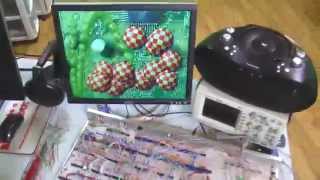
Here is a current sitrep, showing where the board is at, and how real estate is currently divided.

Image
The XMega-384 is running low on IO pins!

Since all of the IO from the various subsystems are not multiplexed at this time, the AVR being used as a "6502 stand-in" has to deal with 42 separate IO lines, and this is without the 32 more that the sound system will require! The IO will later be mapped to a 256 byte address block for the 6502, but for now I need a microprocessor with some serious IO ability, which is why I am using the XMega-384. Once the video section is working the way I want, multiplexing will be added and then the 6502. The sound system will be developed under 6502 control once one channel is working. All 4 channels are exact copies of one another, you know... SID style!

To deal with the Vulcan Logic being at 5 volts, I just over-volted the 3.3 volt XMega!

Image
The PlayField Generator layout on the breadboard.

As things progress, I often move chips around to add new features that were not in the original plan. The PlayField Generator was actually not in the original plan, but will give Vulcan-74 some serious ability to make huge scrolling games without having to resort to tile mapping. The PlayField was going to be a 1024x1024 bitmap that can be scrolled to any position, but I decided to add a little trickery to make it size selectable between 2048x512, 1024x1024, and 512x2048. The Mode Select hardware is a 2-4 decoder that turns on one of the three 74HC245s, driving different pairs of high address bits to the counters.

X and Y Source counters are presetable 74HC193 counters, setup as 12 bits each. Using the Mode Select, each counter set can output 9,10, or 11 bits to the PlayField Memory, which is 1024k, addressed as a pair of bits between 0 and 11 btis in width.

X and Y Destination counters are 74HC590 counters that drive the Source Bitmap date directly to the 400x300 Back Buffer Memory at 20MHz. As these counters wrap at their borders, they advance or reload the Source Counters to their set values, which is why the massive bitmap can be blasted to the screen at any position. So it's kind of like looking at a huge poster through the end of a cardboard tube, you can only see part of the image depending on where you position the viewport.

The PlayField operation also clears the screen for the Sprite Generator, to redraw everything at 60 frames per second.
For a single color blank screen, it's just a matter of writing that color to 400x300 worth of the PlayField Memory.

Image
Vulcan-74 Country and its 3 Provinces.

Vulcan-74 has grown into a very large Nation of silicon very quickly. It's almost funny when I originally planned to have both the video and sound systems all on the same breadboard! This entire board will be filled by the time I add the IO system, and the Sound System will require a board of about 2/3 the size of this one! It's going to be fun looking for PCB manufacture to make the estimated 18x12 sized board! I could make smaller boards and stack them, but one of my goals is to show off the entire board through a glass top cabinet, so a flat single PCB layout is the only layout I will allow. Oh well, I am not afraid to hand wire the entire system point-2-point if I need to.

As per the above photo, the board is divided into three subsystems...

[Red Sector = VGA Generator]
This is the VGA Video Generator. This system tuns independently of the CPU, and draws a VGA frame following the 800x600@60Hz VESA standard exactly. The resulting image is 400x300 with 256 colors, split into a RRR-GGG-BB color space of RED(3 bits), GREEN(3 bits), and BLUE(2 bits). The Video Generator has its own dual banks of 10ns 120K memory, which are auto swapped on the next Vertical Sync by toggling the "Flip" IO line. The CPU can flip screens, as well as reading and writing directly to the back buffer, one pixel at a time. The video system contains the single 20MHz clock oscillator the drives the entire board.

[Yellow Sector = Sprite Generator]
The Sprite Generator contains its own 1024k 10ns SRAM, and can draw blocks of memory (Sprites) to the Back Buffer without any CPU intervention. The CPU simply tells the Sprite Generator the X and Y dimensions of the Sprite in the memory (Source), and the X and Y location on the Back Buffer (Destination). An "Alpha" color is also set, which is an ignored pixel to allow transparency. With the locations set, the Sprite Execution is only single IO line toggle, and the CPU is then free to do whatever it wants as the Sprite is drawn at a speed of 5MHz to the back buffer. Sprites can be of any number and size. Currently, the Sprite Generator can manage about 100 Sprites of 32x32 before the frame rate drops from 60 to 30. Even at 15 FPS, games would still be fine, so there is no lack of power.

[Blue Sector = Playfield Generator]
The purpose of the Playfield Generator is to overlay a full 400x300 screen onto the Back Buffer at high speed.
The Playfield, can be scrolled in any direction, any number of pixels, and can be set to the following sizes...
Mode 0: 1024x1024 - Square or static Playfield
Mode 1: 2048x512 - Good for horizontal scrolling games.
Mode 2 : 512x2048 - Good for vertical scrolling games.


Here is a HUGE photo of the board as of today...
http://lucidscience.com/temp/vt85l.jpg


My next block of free time (scarce) will be used to wire up (nicely) the PlayField Generator for a full test.
The next video will show the true power of Vulcan-74, and what can be done with two fist fulls of logic chips!
... ok, maybe three fist fulls, but still comparable in cost to doing the same with a Spartan-6 FPGA.

Cheers!
Radical Brad


Top
 Profile  
Reply with quote  
PostPosted: Sun Aug 30, 2015 8:53 pm 
Offline
User avatar

Joined: Mon May 25, 2015 2:25 pm
Posts: 632
Location: Gillies, Ontario, Canada
10 chords of uncut firewood has been keeping me out of my basement lab for some time now, but I did manage to wire up the Source Address section of the PlayField Generator for a full test of its capabilities. With the Source Address bits connected, the CPU can tell the PlayField Generator where to start copying the 400x300 block of its massive 1024x1024 bitmap to the Back Buffer. This allows for a giant scrollable screen to be drawn right after the next vertical frame sync, effectively clearing the screen and drawing whatever will be the background.

Much like the Sprite Generator, the PlayField Generator is a fully autonomous State Machine with its own 1024K of SRAM and selectable addressing.
The PlayField Generator runs at 10MHz, so it can copy a 400x300 bitmap to the Back Buffer at amazing speed.

Image
PlayField generator with Source Counters connected.

The only thing missing from the Vulcan-74 Graphics System is the PlayField Generator Address Selector, which will allow the giant stored bitmap to be either 1024x1024, 2048x512, or 512x2048 in size. The ability to adjust the shape of the PlayField image will make it easier to program games or demos that require square, or rectangular scrolling backgrounds.

Image
A massive 1024x1024 Background scrolling.

Well, I was pleasantly surprised when i flipped the switch on after adding the new wiring and seeing everything work perfectly!
Usually I forget a wire or tangle up one of the many bits in the address lines. Not this time... sheer luck!

To get the HUGE 1024x1024 into the PlayField Generator Memory, I had to jump through a few hoops since there is no Serial Flash available yet.
I cut the image into 512x512 chunks and then loaded them into the SRAM one at a time, reprogramming the XMega for each of the 4 chunks!
Since the memory is left intact during an AVR reprogramming, I just changed the address each time to make up the large 1024x1024 image.
When the Loading System is completed, PlayField Images will just be boot loaded on powerup, so the CPU does not have to work hard!
PlayField Memory, like Sprite and Video memory is also directly readable and writable by the CPU for direct access.

So I must declare the Vulcan-74 a total success so far!!
I didn't even plan on having the PlayField Generator, but it sure adds a lot of power.

As promised, a video showing a bunch of Sprites and a 1024x1024 scrolling background...

Image
https://youtu.be/3fXuFCxMHVI

Too bad the uploaded video looks so grainy. The real deal is crisp, smooth, and jitter free!

To move the PlayField Bitmap, the AVR only needs a single line of code in the C Main Loop...

Code:
RunPlayfield(X,Y);


The assembly library is also very simple, as it only has to tickle bits on the main board.
I am only running the AVR at 4MHz, so at 20MHz, the 6502 should have no problems!

Ok, not sure when the next update will be, but things are coming together nicely.
It's time to clean up the new wires by trimming them into nicely wrapped bundles, keeping cross talk and capacitance in mind.
If you design around certain issues, a breadboard can certainly pump 100 ICs up to 20Mhz. This build is proof!

I will be totally out of board space once the 6502 and multiplexing is added, so the Sound System will need another board.
I still have my original 15 panel board available, so I will probably join them together by another 50 feet of wire!

Oh, and 10 points to anyone that can identify the PCB scrolling in the Demo Video!

Cheers!
Radical Brad


Top
 Profile  
Reply with quote  
PostPosted: Tue Sep 01, 2015 12:02 am 
Offline
User avatar

Joined: Mon May 25, 2015 2:25 pm
Posts: 632
Location: Gillies, Ontario, Canada
Detour.

Since the PlayField Generator worked so well on the first incantation, I have decided to do the most logical thing... rip it out and redesign it!

On my hourly commute home from the city today, I was thinking about the arrival of bits through my various chips as the yellow lines on the road blinked past.
Leaving half my brain to concentrate on the road ahead, the other half thought of ways to improve the PlayField Generator.

The PlayField Generator works perfectly at 12.5 MHz (running at 10Mhz now), which was expected knowing the limitations of the chips being used.
I always verify my work by pushing the clock until I see glitches, and the timing held out until about 14Mhz... a little better than calculated form the datasheets.

So my redesign is going to steal some of the ideas that went into the Video Generator, using 74HC574 gates to register data below 50ns, to allow a higher clock speed.
Knowing the total pulse to output limitations of the cascaded 74HC193 counters, I calculate that I can easily push the PlayField Generator up to 16Mhz safely.

The new design will use a 2 "Phase" system, having the data registered after the counters and PlayField Mode Select portion of the circuit.
This puts the absolute worst case propagation to 62ns, which is still within limits of a 16Mhz clock.

I will have to add half a dozen more ICs to the board, but the speed increase is well worth the pin count.
Going from 10Mhz to 16Mhz will give the GPU 6 Million Pixels more per frame, which at 60 FPS equates to a dozen more large Sprites!
Does a game system that can draw 50 large sprites and a 1024x1024 background 60 times per second really need 12 more Sprites?

.... Hell Yeah!

So I am off to grab a fistful of wires from the PlayField Generator section of the board and rip 'em all out with reckless abandon.

Radical Brad


Top
 Profile  
Reply with quote  
Display posts from previous:  Sort by  
Post new topic Reply to topic  [ 733 posts ]  Go to page Previous  1 ... 5, 6, 7, 8, 9, 10, 11 ... 49  Next

All times are UTC


Who is online

Users browsing this forum: No registered users and 7 guests


You cannot post new topics in this forum
You cannot reply to topics in this forum
You cannot edit your posts in this forum
You cannot delete your posts in this forum
You cannot post attachments in this forum

Search for:
Jump to: