6502.org Forum  Projects  Code  Documents  Tools  Forum
It is currently Sun Apr 28, 2024 6:55 pm

All times are UTC


Post new topic Reply to topic  [ 55 posts ]  Go to page Previous  1, 2, 3, 4  Next
Author Message
PostPosted: Thu Nov 30, 2023 2:54 pm 
Offline

Joined: Wed Nov 22, 2023 1:10 pm
Posts: 3
Hi Jeff,

Yea, that's actually the eBay seller that I bought my 68000 board from! unfortunately I missed that one and there was only the one without the keypad left behind.

I will trace out the signals on the interconnect and try to work out what goes where, the ICM7228 will be the easy part, I'm guessing that the keypad has a multiplexed output with a strobe signal which drives the diodes, however it's the connections underneath and between the buttons which will be the tough ones to work out.

From memory, when you power up these systems, the LED will display "rEAdY". If I can work out the button which gets into the memory editor then the numbers will be easy to work out, the rest of the keys should be do-able eventually.

Regards, Dave.


Top
 Profile  
Reply with quote  
PostPosted: Sun Dec 17, 2023 10:41 pm 
Offline

Joined: Sun Dec 17, 2023 10:06 pm
Posts: 1
Hi Dave,
I just came across this site when I was looking for info on the 6502 MACH III board. I have a working one which I acquired a few years back to go with my small collection of trainer type computers. It was an Ebay purchase where the guy was selling them as scrap parts boards; I don't think that he realised that they made self contained computers when the right boards were put together. I have 6502 MACH 111, a keyboard/display, and the applications module. The keyboard/display is the Digiac 3000 'Microprocessor Master Board' rather than the smaller Digiac 2000 keyboard/display unit but it looks like they are pretty much identical circuitry just on a bigger panel that the 6502 board rests on top of and with an extra 5V power supply. (See the brochure that was posted earlier in this thread). With a +5V supply plugged direct to the Digiac 2000 6502 board and the ribbon cable to the keyboard unit it all works fine (i.e. displays 'ready' and reponds to the keys).

If you haven't already worked out the keyboard and display connections let me know and I will make an image of the board. It's a simple single sided PCB with a few top side links, diodes, resistors and the display controller chip.

Regards,
Nick


Top
 Profile  
Reply with quote  
PostPosted: Tue Dec 19, 2023 6:08 pm 
Offline
User avatar

Joined: Fri Dec 11, 2009 3:50 pm
Posts: 3349
Location: Ontario, Canada
Great stuff, Dave! This could really make a big difference. :!: But, hmm, so far, no word back from Davegsm1982... :|

Anyway, welcome! And thanks for jumping in with the generous offer of assistance. We'd be delighted if you get a chance to hang out here in future and get acquainted.

-- Jeff

_________________
In 1988 my 65C02 got six new registers and 44 new full-speed instructions!
https://laughtonelectronics.com/Arcana/ ... mmary.html


Top
 Profile  
Reply with quote  
PostPosted: Mon Jan 15, 2024 8:20 am 
Offline
User avatar

Joined: Thu Dec 11, 2008 1:28 pm
Posts: 10793
Location: England
It looks like we've had several offers of ROM dumps, but as yet I don't any ROM dumps have yet been shared. I do hope someone will do that favour!

(It's possible to upload anything to the Internet Archive, and even to do it using an anonymous disposable email address, so this is one way to ensure there's a public record of data like this. Just be sure to put enough information in the tags and description to make it findable!)

I see Hans has collated and posted some scans of manuals and brochures for the Digiac series at
http://retro.hansotten.nl/6502-sbc/emma ... 2-systems/


Top
 Profile  
Reply with quote  
PostPosted: Mon Feb 05, 2024 7:59 am 
Offline

Joined: Mon Feb 05, 2024 7:06 am
Posts: 9
Hi my name is Joseph,

I have one of these MACIII 6502 trainer boards with a keypad display and an applications module.
I managed to dump the rom using a microcontroller.
The board is working fine using the keypad.

My question to you guys is has anyone managed to successfully connect to the board via the CH.A serial port?

I have tried using an ftdi serial to usb converter but I get nothing but garbage, I tried all baud rates from 300 to 115200.
After doing some testing with a dmm I believe that the serial port is probably non standard ie. not rs232.

pin 3 of the 9 pin D-Sub is connected to ground,
TX1 and TX2 of the MAX232 chip are connected to pins 1 and 2.
RX1 and RX2 of the MAX232 chip are connected to pins 6 and 7.

The standard 9pin rs232 serial port pinout is :

1 ---------- DCD
2 ---------- RXD
3 ---------- TXD
4 ---------- DTR
5 ---------- GROUND
6 ---------- DSR
7 ---------- RTS
8 ---------- CTS
9 ---------- RI
I would appreciate any pointers.

Joseph


Top
 Profile  
Reply with quote  
PostPosted: Mon Feb 05, 2024 8:08 am 
Offline
User avatar

Joined: Thu Dec 11, 2008 1:28 pm
Posts: 10793
Location: England
Welcome Joseph! It would be excellent if you could share your ROM dump, perhaps by attaching a zip or by putting it on Dropbox or similar.

Does your ftdi converter work with other serial connections? Every usb to serial converter seems to have its own quirks and difficulties. I think it's very likely that the serial protocol is a standard one, although it's possible the voltages are not working with your adapter. And it looks like the D-sub pinout is non-standard. Do you have the means to make direct connections with GND and TXD? That would be a good start, and would be enough to see data from the board. (It's very common to mix up TX and RX, so always try both.)

I'd suggest you read off the voltages of each pin of both the A and the B channels, when idle.

Do you have a frequency-counting mode in your multimeter? We can probably find a way to find the baud rate with that.


Top
 Profile  
Reply with quote  
PostPosted: Tue Feb 06, 2024 12:08 pm 
Offline
User avatar

Joined: Thu Dec 11, 2008 1:28 pm
Posts: 10793
Location: England
I'm reliably informed the serial connection is 8 data bits, no parity, 2 stop bits at 9600 baud. Hope this helps!


Top
 Profile  
Reply with quote  
PostPosted: Tue Feb 06, 2024 3:57 pm 
Offline

Joined: Mon Feb 05, 2024 7:06 am
Posts: 9
Thanks Big Ed,


I thought it probably was 9600, still no luck though, this is the output to the serial monitor. :

00000000 00 9E 96 2D 73 A5 93 27 C9 24 4B 39 7A 39 F2 93 ...-s..'.$K9z9..
00000010 A5 48 23 91 4D 49 19 7E CA FA C9 C9 E6 33 A6 99 .H#.MI.~.....3..
00000020 66 E6 F3 33 65 66 9A 33 79 EB D6 CA CA F9 73 84 f..3ef.3y.....s.
00000030 72 72 B2 A4 93 23 46 83 7E 4A 7E 7E EE 69 92 E4 rr...#F.~J~~.i..
00000040 E4 92 D2 C8 53 49 93 49 48 1B 1A F9 93 12 C9 92 ....SI.IH.......
00000050 91 4D 24 91 46 33 B2 24 92 92 73 E4 49 93 93 E4 .M$.F3.$..s.I...
00000060 A4 93 27 4B 33 5A A9 72 F2 D3 72 72 B2 A4 93 23 ..'K3Z.r..rr...#
00000070 46 E5 D6 F2 F9 73 4C 72 72 B2 A4 93 23 46 83 7E F....sLrr...#F.~
00000080 4A 7E 7E F2 79 D2 32 49 93 4D 53 49 93 49 48 1B J~~.y.2I.MSI.IH.
00000090 1A F9 93 12 C9 92 91 4D 24 91 46 D3 72 E4 73 E4 .......M$.F.r.s.
000000a0 49 93 93 E4 A4 93 27 4B 99 5A 6A D8 F2 D3 72 72 I.....'K.Zj...rr
000000b0 B2 A4 93 23 46 79 EB E2 F9 73 A6 72 72 B2 A4 93 ...#Fy...s.rr...
000000c0 23 46 83 7E 4A 7E 7E EA 79 52 92 52 E4 91 93 D3 #F.~J~~.yR.R....
000000d0 F2 F3 64 24 92 26 23 4F 25 7E 66 D9 12 49 92 73 ..d$.&#O%~f..I.s
000000e0 E4 49 93 93 E4 A4 93 27 4B 33 5A A9 72 F2 D3 72 .I.....'K3Z.r..r
000000f0 72 B2 A4 93 23 46 E5 D6 AE F9 73 4C 72 72 B2 A4 r...#F....sLrr..
00000100 93 23 46 83 7E 4A 7E 7E AE D9 D2 92 52 F2 D3 C9 .#F.~J~~....R...
00000110 92 46 91 23 45 39 2E 69 12 C9 92 D3 72 E4 93 E4 .F.#E9.i....r...
00000120 A4 93 27 4B 33 5A A9 72 F2 D3 72 72 B2 A4 93 23 ..'K3Z.r..rr...#
00000130 46 BF 7A 19 72 F2 73 D2 49 E4 E4 92 D2 C8 B3 A4 F.z.r.s.I.......
00000140 93 26 4B 19 2E A9 B2 24 A4 9E 3D 96 F3 F3 F3 F3 .&K....$..=.....
00000150 F3 F3 F3 F3 F3 F3 53 CD F3 73 4B 92 4F 93 33 D2 ......S..sK.O.3.
00000160 C9 92 4D 33 B2 24 92 92 93 D2 92 24 A4 93 91 91 ..M3.$.....$....
00000170 4D 13 C9 E4 B3 25 65 26 66 E6 D3 C9 92 91 48 53 M....%e&f.....HS
00000180 49 93 92 48 23 43 79 EB DE 52 7E 7E 7E 7E 7E 7E I..H#Cy..R~~~~~~
00000190 7E 7E 7E 7E 4A 7E 7E EE 69 92 E4 E4 92 D2 C8 73 ~~~~J~~.i......s
000001a0 E4 49 93 33 52 E4 92 92 F3 49 93 92 E4 93 24 B2 .I.3R....I....$.
000001b0 A4 93 93 24 79 EB D6 CA CA E9 C9 59 E6 03 00 ...$y......Y...

This is what the logic capture looks like:

Attachment:
Digiac_logic_capture.png
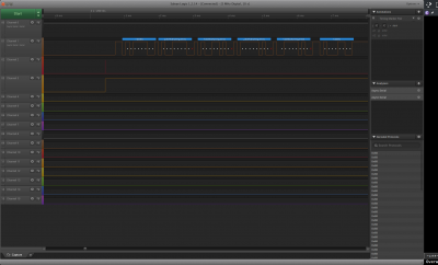
Digiac_logic_capture.png [ 165.65 KiB | Viewed 622 times ]


Top
 Profile  
Reply with quote  
PostPosted: Tue Feb 06, 2024 4:08 pm 
Offline
User avatar

Joined: Thu Dec 11, 2008 1:28 pm
Posts: 10793
Location: England
Looks to me like your analyser is interpreting an inverted logic. I think the first L-H transition is the start bit. Somewhere in the chain of hardware and software and probing it looks like there needs to be an inversion.

I think it's the case that RS232 does use the lower voltage - a negative voltage - for logic 1, and the higher voltage for logic 0.

Perhaps see here: https://www.sparkfun.com/tutorials/215


Top
 Profile  
Reply with quote  
PostPosted: Tue Feb 06, 2024 5:11 pm 
Offline

Joined: Mon Feb 05, 2024 7:06 am
Posts: 9
]I tried sending a bunch of ascii 'k's to the board using the serial monitor, my logic analyser interpreted those correctly.

[attachment=0]Logic_Analyser-Digiac_RX-k.png[/attachment

I've ordered a pci express serial card that I can put in an old pc that i have lying around, maybe that will yield different results.


Attachments:
Logic_Analyser-Digiac_RX-k.png
Logic_Analyser-Digiac_RX-k.png [ 152.18 KiB | Viewed 615 times ]
Top
 Profile  
Reply with quote  
PostPosted: Tue Feb 06, 2024 5:16 pm 
Offline
User avatar

Joined: Thu Dec 11, 2008 1:28 pm
Posts: 10793
Location: England
Hmm. Could you clarify perhaps - you've posted two traces. Are they both voltages sent by the Digiac, or both sent by your FTDI adapter, or one of each?

(Also, you pasted a hex dump, but I don't know what it represents: which system sent those bytes? Did the system send the hex dump as we see it, with the printable characters, or did it send the bytes represented within, such as 00, 9E, 96?)


Top
 Profile  
Reply with quote  
PostPosted: Tue Feb 06, 2024 5:36 pm 
Offline

Joined: Mon Feb 05, 2024 7:06 am
Posts: 9
Sorry, the first trace the one on channel 1 of the logic analyser is the txd line coming from the digiac. The second trace, the one on channel 0 is data I sent from the serial monitor on my computer ascii 'k' 0x6b .

the hexdump is the actual data transmitted by the digiac on a cold boot, my serial monitor is capable of displaying the data in hexadecimal.


Top
 Profile  
Reply with quote  
PostPosted: Tue Feb 06, 2024 8:06 pm 
Offline
User avatar

Joined: Thu Dec 11, 2008 1:28 pm
Posts: 10793
Location: England
Ah, thanks. Surprised the digiac sends out a hex dump on cold start. I just might see if I can try to run an emulation.

For the two traces, then, the one where you're looking at the PC sending shows that the logic analyser agrees with the PC on 8-N-1 TTL levels. But I think the other trace shows that the logic analyser doesn't like the RS232 inverted levels with two stop bits. So I think you need to set your PC to send two stop bits, and you need to sort out the inversion somehow.


Top
 Profile  
Reply with quote  
PostPosted: Tue Feb 06, 2024 8:23 pm 
Offline

Joined: Mon Feb 05, 2024 7:06 am
Posts: 9
I agree, I will try it again when the serial card for my pc arrives, maybe the ftdi chip is inverting the signal.


Top
 Profile  
Reply with quote  
PostPosted: Wed Feb 07, 2024 6:41 am 
Offline

Joined: Mon Jan 19, 2004 12:49 pm
Posts: 660
Location: Potsdam, DE
Hang on, are you looking at a UART signal, or an RS232 signal? The polarities are opposite, and the voltages much greater on the RS232. your logic analyser is almost certainly expecting UART levels and polarity.

Neil


Top
 Profile  
Reply with quote  
Display posts from previous:  Sort by  
Post new topic Reply to topic  [ 55 posts ]  Go to page Previous  1, 2, 3, 4  Next

All times are UTC


Who is online

Users browsing this forum: No registered users and 3 guests


You cannot post new topics in this forum
You cannot reply to topics in this forum
You cannot edit your posts in this forum
You cannot delete your posts in this forum
You cannot post attachments in this forum

Search for:
Jump to: