6502.org Forum  Projects  Code  Documents  Tools  Forum
It is currently Sun May 19, 2024 4:06 am

All times are UTC


Post new topic Reply to topic  [ 18 posts ]  Go to page 1, 2  Next
Author Message
PostPosted: Wed Apr 26, 2023 5:09 pm 
Offline
User avatar

Joined: Mon Aug 30, 2021 11:52 am
Posts: 269
Location: South Africa
How do I do it? I'm stumped (because I don't understand analogue signals at all).

I have a 0V to 3.3V analogue signal that I would like to convert to an audio line level -1V to 1V signal.
Attachment:
20230426_184756.jpg
20230426_184756.jpg [ 1.79 MiB | Viewed 194120 times ]
This thing above. It's just a 600Hz saw tooth generated by feeding an 8bit counter into a MAX5102 DAC. Let's say yellow is the right channel. And pink is the left channel outputting the inverse. Green is 0V.

I have an op-amp and an inverting charge pump and I think I should be able to use them level shift the 3.3V signal to at least -1.5V/1.5V. Optionally to also scale it down to two thirds.

Is an op-amp the way to go? I can run it at +ve VDD -ve GND using the charge pump but all I've succeeded in doing is clipping the signal rather than offsetting it into the negative. I've searched the internet for op-amp tutorials and calculators but none have taken a -ve virtual ground into account. And I really do not understand op-amps.

How do I do this? Any help would be most appreciated thanks!


Top
 Profile  
Reply with quote  
PostPosted: Wed Apr 26, 2023 7:36 pm 
Offline
User avatar

Joined: Fri Aug 30, 2002 1:09 am
Posts: 8440
Location: Southern California
What you have there is a triangle wave. A sawtooth wave is like this, with a vertical edge:
Code:
        *        *        *        *        *
        **       **       **       **       *
        * *      * *      * *      * *      *
        *  *     *  *     *  *     *  *     *
        *   *    *   *    *   *    *   *    *
        *    *   *    *   *    *   *    *   *
        *     *  *     *  *     *  *     *  *
        *      * *      * *      * *      * *
        *       **       **       **       **
        *        *        *        *        *
It is extremely rich in harmonics compared to a triangle wave.

For getting the output centered around 0V, all you need is a series DC-blocking capacitor.  The value will depend on the load.  If the load itself doesn't bleed the capacitor down, a bleed resistor from output to ground will do the job.

Since what you're starting with spans 3.3V and what out want to output spans only 2V (ie, -1 to +1), you could do a simple voltage divider with no op amp and no power-supply conversion if you know the load impedance with reasonable accuracy.  Do you know what it will be?

So the whole job may come down to nothing more than a capacitor and a resistor or two.

_________________
http://WilsonMinesCo.com/ lots of 6502 resources
The "second front page" is http://wilsonminesco.com/links.html .
What's an additional VIA among friends, anyhow?


Top
 Profile  
Reply with quote  
PostPosted: Wed Apr 26, 2023 10:29 pm 
Offline
User avatar

Joined: Fri Dec 12, 2008 10:40 pm
Posts: 1001
Location: Canada
He does actually have sawtooth waveforms there on channels 1 and 2 (yellow and purple). One is just the reverse of the other.


Here is sort of what you need:
Attachment:
Voltage divider with DC block.jpg
Voltage divider with DC block.jpg [ 22.04 KiB | Viewed 194075 times ]

_________________
Bill


Top
 Profile  
Reply with quote  
PostPosted: Wed Apr 26, 2023 10:45 pm 
Offline
User avatar

Joined: Fri Aug 30, 2002 1:09 am
Posts: 8440
Location: Southern California
BillO wrote:
He does actually have sawtooth waveforms there on channels 1 and 2 (yellow and purple). One is just the reverse of the other.

Ah—Right you are.  The vertical lines just don't show, for whatever reason.  I would have expected a DSO to fill them in.

Quote:
Here is sort of what you need:

I'd recommend putting the capacitor before (to the left of) the resistors, so the driver doesn't have to drive the DC offset into the resistors.  Also, the load impedance will affect what the resistor ratio and values should be.  The load impedance and R2 (ie, the bottom resistor) will combine to make the bottom portion of the voltage divider, meaning the output voltage will be:
      3.3V * ( 1/(1/ZL+1/R2) / (1/(1/ZL+1/R2) +R1)
The ZL, ie, load resistance, can be complex (ie, have a capacitive or inductive component), and as long as complex-number arithmetic is used, the equation will still work correctly.  The equation assumes the capacitor value is sufficiently large that we can ignore its reactance at even the lowest frequency of interest.

_________________
http://WilsonMinesCo.com/ lots of 6502 resources
The "second front page" is http://wilsonminesco.com/links.html .
What's an additional VIA among friends, anyhow?


Top
 Profile  
Reply with quote  
PostPosted: Wed Apr 26, 2023 11:42 pm 
Offline
User avatar

Joined: Fri Dec 12, 2008 10:40 pm
Posts: 1001
Location: Canada
GARTHWILSON wrote:
Ah—Right you are. The vertical lines just don't show, for whatever reason. I would have expected a DSO to fill them in.

They are there, just difficult to se. The channel that is active in the control group is the purple one, so it's going to be "on top". Unfortunately it's much harder to see than the yellow.

Edit: It would show a lot better if he did a proper screen capture too.

GARTHWILSON wrote:
I'd recommend putting the capacitor before (to the left of) the resistors, so the driver doesn't have to drive the DC offset into the resistors.

Good idea.

GARTHWILSON wrote:
Also, the load impedance will affect what the resistor ratio and values should be.  The load impedance and R2 (ie, the bottom resistor) will combine to make the bottom portion of the voltage divider, meaning the output voltage will be:
      3.3V * ( 1/(1/ZL+1/R2) / (1/(1/ZL+1/R2) +R1)
The ZL, ie, load resistance, can be complex (ie, have a capacitive or inductive component), and as long as complex-number arithmetic is used, the equation will still work correctly.  The equation assumes the capacitor value is sufficiently large that we can ignore its reactance at even the lowest frequency of interest.[/color]

Of course! But I did say "sort of" 8)

_________________
Bill


Top
 Profile  
Reply with quote  
PostPosted: Thu Apr 27, 2023 10:07 am 
Offline
User avatar

Joined: Mon Aug 30, 2021 11:52 am
Posts: 269
Location: South Africa
GARTHWILSON wrote:
For getting the output centered around 0V, all you need is a series DC-blocking capacitor.  The value will depend on the load.  If the load itself doesn't bleed the capacitor down, a bleed resistor from output to ground will do the job.
That's perfect thanks! In the end I used a 0.1μF MLCC cap (because it's the smallest I have but I suspect smaller would be fine [EDIT] - a 0.01μF MLCC cap was not fine). And I also needed a 1MΩ bleed resistor, anything smaller caused the signal to 'warp'.

I changed the DACs reference voltage from 3.3V to 2.2V and that gave me a suitably scaled analogue output signal.

However plugging the output into my amplifiers Line In dragged it's voltage to zero. I tried a bigger DC-blocking cap and another MΩ resistor in series after it but that just gave me a rounded signal that still went to zero when plugged into the amp.

In the end I brought the op-amp back again and used it to buffer my signal giving me a final schematic:
Attachment:
Audio DAC schematic.png
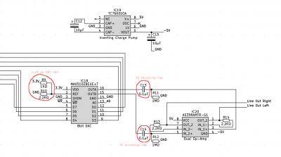
Audio DAC schematic.png [ 67.12 KiB | Viewed 194030 times ]

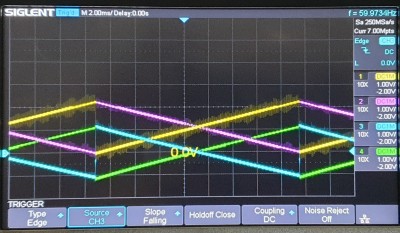
and a signal (into the speaker amplifier) of:
Attachment:
Audio DAC waveform.jpg
Audio DAC waveform.jpg [ 1.39 MiB | Viewed 194030 times ]
The blue and green traces are the level shifted outputs and seem to remain pretty stably centered around 0V.

BillO wrote:
Here is sort of what you need: ... Of course! But I did say "sort of" 8)
Thanks BillO! In the end I just poked roughly valued components in until I got a decent signal :D
(Oh, the oscilloscope is not drawing the vertical saw tooth line nicely because I left the scope in 'dotty persistent' mode rather than line mode.)

And no post is complete without the messy breadboard, the MAX5102 is hidden behind the mass of jumpers on the right
Attachment:
Audo DAC boad.jpg
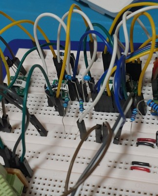
Audo DAC boad.jpg [ 1.18 MiB | Viewed 194030 times ]


Top
 Profile  
Reply with quote  
PostPosted: Thu Apr 27, 2023 4:18 pm 
Offline

Joined: Mon Jan 19, 2004 12:49 pm
Posts: 690
Location: Potsdam, DE
Andrew, your 'signal dragged down to zero' suggests a significant impedance mismatch. Generally audio signals are fed into a circuit with a defined but fairly low impedance - 600 ohms is standard in broadcasting and probably throughout the recording industry - and so need to be delivered from an output with a very low impedance. An op-amp delivers that low-impedance output that you need.

Just to be different, 'DIN' connectors on domestic audio are (were?) usually defined as much higher input impedances; tens of k ohms. These are less sensitive to the output impedance of the driving signal.

Neil


Top
 Profile  
Reply with quote  
PostPosted: Thu Apr 27, 2023 7:14 pm 
Offline
User avatar

Joined: Mon Aug 30, 2021 11:52 am
Posts: 269
Location: South Africa
barnacle wrote:
... a significant impedance mismatch. Generally audio signals are fed into a circuit with a defined but fairly low impedance - 600 ohms
I'd guess so? I know very little about impedance. I don't know what the output impedance is to match it to the 600Ω input impedance. The datasheet mentions a 10KΩ in parallel with a 100pF load but I think that's just to work out a standard DAC settling time.

With that said my contribution to this is a link to an

ONLINE SMITH CHART TOOL

that can be run offline by following instructions at the

EEVblog Electronics Community Forum

For now I've got no tools, or even variable capacitors or inductors, that would help me troubleshoot this so it shall have to remain an op-amp.

Impedance matching is definitely something I'm going to have to learn so I'm glad you've let me know.

Cheers,
Andrew!


Top
 Profile  
Reply with quote  
PostPosted: Thu Apr 27, 2023 7:53 pm 
Offline
User avatar

Joined: Fri Aug 30, 2002 1:09 am
Posts: 8440
Location: Southern California
In audio, you generally want the output impedance of a source to be much, much lower than the input impedance of a load.  The Smith chart is for RF and transmission lines.  It is not at all what you want for this.  (I had to be really cozy with the Smith chart when I worked in applications engineering at a place that made VHF & UHF power transistors in the mid 1980's, mostly for military radars and communications.)  Tell me what you want to drive with this circuit, and I can probably get you fixed up.  You generally won't want your R13 and R14, but rather just make those hardwire connections; but depending on the load, you might need an output resistor or 100Ω or so.  This is not for impedance-matching, but rather for avoiding oscillation under certain conditions which I won't go into here as it's way beyond a beginner's level.  From the data sheet, it looks like "AS358..." is just Diodes, Inc.'s designation for their LM358 which is a belly-button part (ie, everybody has one, like TI, ST Microelectronics, Diodes, Inc., ON Semi, Rohm, etc.).  I've used it in countless circuit designs, and over the decades have gotten familiar with nuances that don't come through in most data sheets.

_________________
http://WilsonMinesCo.com/ lots of 6502 resources
The "second front page" is http://wilsonminesco.com/links.html .
What's an additional VIA among friends, anyhow?


Top
 Profile  
Reply with quote  
PostPosted: Fri Apr 28, 2023 2:00 pm 
Offline
User avatar

Joined: Mon Aug 30, 2021 11:52 am
Posts: 269
Location: South Africa
GARTHWILSON wrote:
Tell me what you want to drive with this circuit, and I can probably get you fixed up. You generally won't want your R13 and R14, but rather just make those hardwire connections; but depending on the load, you might need an output resistor or 100Ω or so.
Thank you muchly. I think this is it. I want to drive any standard audio line-in device.

I've made the changes you suggested and if using an op-amp is not a bad way to deal with the impedance matching issue then I think I'm done. Both the op-amp and the charge pump are so cheap that, even if overkill, I don't mind using them. If not right then any more suggestions would be most appreciated.

At a slightly higher level what I'm trying to do is create a generally useful digital sound device. Something that could be easily interfaced with anything that can output an 8bit signal.

To do that it's almost as simple as four 74HCT40105s sitting on the data bus*. Their outputs are ticked at a constant 16KHz (for 16Khz 8bit stereo sound) and fed into the MAX5102. In my case I have a 2KHz NMI derived from the same 32KHz clock that ticks the '40105s which I use as a general watchdog / OS timer thing. As long as I can feed two times 8 bytes into the '40105s every NMI then... sound.
Attachment:
Audio DAC schematic 2.png
Audio DAC schematic 2.png [ 111.18 KiB | Viewed 193936 times ]
I've marked the changes I made in red but I forget I also added a bypass cap between the MAX5102 REF and GND (suggested by the datasheet).

That's intentionally a VHC flip-flop. At KHz speeds it should handle 3.3V VCC just fine - and I have a few knocking around that I picked up for something like a US cent each.

*Address decoding sold separately

[EDIT - I just realised the 10μF cap between -5V and ground is backwards. Ground is relatively positive here.]


Last edited by AndrewP on Wed Jul 19, 2023 12:04 pm, edited 1 time in total.

Top
 Profile  
Reply with quote  
PostPosted: Fri Apr 28, 2023 10:09 pm 
Offline
User avatar

Joined: Fri Aug 30, 2002 1:09 am
Posts: 8440
Location: Southern California
AndrewP wrote:
GARTHWILSON wrote:
Tell me what you want to drive with this circuit, and I can probably get you fixed up. You generally won't want your R13 and R14, but rather just make those hardwire connections; but depending on the load, you might need an output resistor or 100Ω or so.
Thank you muchly. I think this is it. I want to drive any standard audio line-in device.

I think you'll still want to look into whatever it is you want to drive.  "Standard" input devices, like an amplifier's line inputs, used to take much higher voltages than you're going to be outputting there.  When I worked at TEAC, .316V RMS (ie, SQRT(10)/10, for -10dBV) was considered line level for the high-impedance audio stuff.  Much of the high-end home-audio industry shared this level.  .316V RMS is .894V peak-to-peak (which I'll abbreviate Vpp) for a sine wave, so if you add 20dB for headroom, you get 8.94Vpp.  That amount of headroom is kind of a minimum for music; but if you only have 8-bit samples, you'll probably have a fair amount of dynamic compression, or at least a lot less dynamic range, making life a little easier in that department.  These devices usually (but not always) have/had input gain adjustment knobs, so hopefully you could bring your weak signal up to the desired level.  (However, a higher level helps get over the hums and other noises that could couple in from cables and less-than-ideal ground schemes.)

Back in the day, I've seen even phono cartridge pre-amps that could put out 40Vpp.  Studio and high-end audio stereo headsets are generally 300Ω per ear (so is our aircraft stuff), and generally need whatever drives them to be able to swing at least 10Vpp to get good volume without clipping on the peaks.  Ear buds' input voltages have come way down though because of power-supply limitations on the tiny battery-powered devices that drive them, so these are often 8Ω, getting the necessary power from greater current rather than voltage.  Someone mentioned professional studio equipment which regards +4dBm into 600Ω as line level, which is .775V (even though loads are usually much lighter).  [Whoops—See my correction in my next post, below. :oops:20dB of headroom would require being able to swing 22V.  30dB of headroom would require being able to swing 69V.  I doubt you're interested in professional studio equipment, so this is just some reference information for orientation.  Pro audio was one of my intense interests in the 1970's and early 80's, and I got a useless degree in recording arts technology.

Quote:
I've made the changes you suggested and if using an op-amp is not a bad way to deal with the impedance matching issue then I think I'm done. Both the op-amp and the charge pump are so cheap that, even if overkill, I don't mind using them. If not right then any more suggestions would be most appreciated.

There are so many op amps and D/A converters on the market that it's impossible to be familiar with a significant percentage of them.  I've taken a quick look at the MAX5102 D/A converter, but I can't take the time to really dig into the details.  If the output voltage swing is adequate for what you want to drive, just put a series capacitor on the output, with a bleeder to ground out the output from that capacitor so the final output will be centered on 0V, and omit the 358 op amp.  The D/A apparently has internal rail-to-rail op amps at the output anyway.  I would still put a 100Ω resistor in series with the output capacitor as I mentioned earlier.  It's possible the internal op amps could handle a lower-value resistor ok and remain stable regardless of what load is past that; but 100Ω is low enough that it won't have any significant effect on any active circuitry you might want to drive with it.  If you do leave the 358 there with a charge pump to supply the negative voltage, you might want to consider the charge pump's operating frequency (10kHz typ for your 7660) and the PSRR (power-supply rejection ratio) of the 358 at that frequency and see if there could be irritating effects of beating with your sampling frequency and intended output signals.

And speaking of the sampling frequency:  The maximum audio frequency you can get with a 16kHz sampling is below 8kHz (the Nyquist frequency), which is a lot better than many people think, but if you don't have some sort of output anti-alias filtering, the images above 8kHz resulting from aliasing could have some strange effects.  For example, frequency content at 5kHz would also show up at 11kHz, frequency content at 6kHz would also show up at 10kHz, etc..  It's hardly a concern at the lower frequencies though, for a couple of reasons.  The wikipedia article has an audio demo at https://en.wikipedia.org/wiki/Aliasing#Audio_example .

_________________
http://WilsonMinesCo.com/ lots of 6502 resources
The "second front page" is http://wilsonminesco.com/links.html .
What's an additional VIA among friends, anyhow?


Top
 Profile  
Reply with quote  
PostPosted: Sat Apr 29, 2023 6:11 am 
Offline

Joined: Mon Jan 19, 2004 12:49 pm
Posts: 690
Location: Potsdam, DE
A difference between UK/Euro and US pro audio standards: we usually defined 0dBm as 775mV into 600 ohms as zero level. A broadcast PPM (signal level meter) had zero level at an indicated 4 on the meter; other marks were 4dB apart. Most audio amplifiers in the BBC used 24v supplies.

US and Euro systems wire XLR audio jacks differently, too...

Neil


Top
 Profile  
Reply with quote  
PostPosted: Sat Apr 29, 2023 6:31 am 
Offline
User avatar

Joined: Fri Aug 30, 2002 1:09 am
Posts: 8440
Location: Southern California
barnacle wrote:
A difference between UK/Euro and US pro audio standards: we usually defined 0dBm as 775mV into 600 ohms as zero level.

Big goof on my part.  :oops:   Yes, .775V into 600Ω is 1mW; but the line level in our studios is 4dB above that, or about 2.5mW, or, more accurately, 1.228V, since the loads were usually much, much lighter than 600Ω, so you could put several loads on one output and not be overloading it.  The other numbers should be adjusted accordingly; so for example +20VU (for headroom) would be 12.28V RMS which is nearly 35Vpp for a sine wave.

Quote:
US and Euro systems wire XLR audio jacks differently, too...

I don't know how the Europeans use XLR's; but I know that in non-pro equipment, Europe was using the DINs while the US was using RCAs.  I do remember that when I used to go to the Audio Engineering Society (AES) conventions, I'd see European equipment that had a different kind of connector.

_________________
http://WilsonMinesCo.com/ lots of 6502 resources
The "second front page" is http://wilsonminesco.com/links.html .
What's an additional VIA among friends, anyhow?


Top
 Profile  
Reply with quote  
PostPosted: Sat Apr 29, 2023 12:12 pm 
Offline

Joined: Mon Jan 19, 2004 12:49 pm
Posts: 690
Location: Potsdam, DE
Euro/UK XLR audio wiring is pin 1 shield, pin 2 in phase, pin 3 antiphase (balanced signal of course); US wiring swaps pin 1 and 2 IIRC. It all sorts of works until someone puts phantom power on it :mrgreen:

Our output impedances were usually well below 10 ohms but always 600 ohms in.

It's only in recent years that Euro domestic equipment moved away from din-3 and din-5 connectors to phono jacks (RCA) - largely the influence of Far Eastern audio equipment. Of course, if you look at an old Quad II amp, you'll find a Jones socket on the side...

It's been a few years now but I spent over thirty years as a BBC engineer in various capacities.

Neil


Top
 Profile  
Reply with quote  
PostPosted: Sat Apr 29, 2023 12:36 pm 
Offline
User avatar

Joined: Mon Aug 30, 2021 11:52 am
Posts: 269
Location: South Africa
Things I've learned. Audio is hard.

Like, seriously.

But back to the topic of just getting a signal into a load and not having the load distort the signal. I pulled the charge pump and op-amp out. The 0.1μF DC blocking cap was way to small. I replaced it with a 47μF cap (and then a 100μF then a 330μF) and then plugged the Line In on the amp directly into it. The signal stayed unchanged.

Yay! Except not.

Audio is hard.

I tried a few different waveforms. And got a high pitch hiss / squeak out of a what I thought would be a nice low frequency triangle wave. The low frequency triangle wave was predominant but it definitely wasn't right. I inserted some 220Ω resistors in series after the caps and that seemed to help. I also tried 1KΩ and 10MΩ just to see hear what would happen. I think for a chosen update frequency of 16KHz it should be possible to smooth out the very sharp steps from the 8bit DAC but I don't know if that's the way to go.

I tried sampling the output sound using my phone and it looked sort of okay. Maybe. There were significant variations between the waveforms' peak-to-peak for that 500Hz triangle wave I was testing with. But the amplified speakers I'm using are an ancient pair of Logitech Desktop Computer speakers. Their sound reproduction could be quite poor. And the mic on my phone probably isn't great either.

Anyway I tried the same triangle waveform on Windows desktop PC using a tone generator and it looked consistent and properly triangular on my phone. And sounded 'purer'. So I guess that answers that, phone mic is good enough.

Except it was played back in 16bit 44Khz. And then the power went out so I had to stop testing.

I think my next step is to move my circuit to a PCB because there seem to be noisy glitches every time the DAC updates and I'm hoping that's a breadboard issue. But I must do it in a way that allows me to test different 'Line Out' boards against my one 'DAC board'. I also need to test with sound that isn't just a tone. That's going to take some proper programming time.

A question on the Nyquist limit. If the inital waveform was sampled at 32KHz but played back at 16KHz would that still be an effective 8KHz or is it 16KHz?

Thanks for all the help!
Andrew


Top
 Profile  
Reply with quote  
Display posts from previous:  Sort by  
Post new topic Reply to topic  [ 18 posts ]  Go to page 1, 2  Next

All times are UTC


Who is online

Users browsing this forum: No registered users and 1 guest


You cannot post new topics in this forum
You cannot reply to topics in this forum
You cannot edit your posts in this forum
You cannot delete your posts in this forum
You cannot post attachments in this forum

Search for:
Jump to: