6502.org Forum  Projects  Code  Documents  Tools  Forum
It is currently Sat Apr 27, 2024 3:18 pm

All times are UTC


Post new topic Reply to topic  [ 62 posts ]  Go to page Previous  1, 2, 3, 4, 5  Next
Author Message
PostPosted: Fri Mar 10, 2023 10:55 am 
Offline

Joined: Fri Jul 09, 2021 10:12 pm
Posts: 741
Yuri wrote:
So I think I may have noticed the issue here. The system comes up and runs, but when I tried plugging the serial cable into the 65C51 it refused to even boot. I started digging and the cheep bread board power supply I have is delivering 8.3V for some reason according to my meter. >_<

So, now to track down a better power supply.

Eek, is it one of the ones that plugs across the power rails and has a USB-A socket as well as a barrel jack? I've had the same thing, for a long time i was running my system at 7-8V as it appeared the voltage regulator had failed. At the time I thought it might have been due to me shorting it at some point, but it's hard to be sure when the system wasn't obviously broken afterwards.

Due to car battery issues in the past I had a device you plug in to the cigarette lighter socket with an LED display of the voltage it sees, which broke, but I took it to bits and rewired it to plug into the breadboard so now I have a permanent voltage display, which is good for peace of mind!


Top
 Profile  
Reply with quote  
PostPosted: Mon Mar 13, 2023 6:39 pm 
Offline
User avatar

Joined: Tue Feb 28, 2023 11:39 pm
Posts: 133
Location: Texas
Okay,

Things are pretty stable. The only issue I've run into is that it seems that if I have the 65C51 hooked up to my PC in anyway, it prevents the 65C02 from starting. It works fine if I connect the PC after the 65C02 has had a chance to start.

I've tried using a DTECH USB to TTL serial converter cable as well as my Arduino Due as a dummy pass thru serial port, and both have the same issue. If they're plugged into the system before power on, the 65C02 won't start. I have to disconnect them and power the thing down (reset doesn't work) and then back up.

I've checked the power rails and they appear to be good. (The current power module is delivering 4.97V)

All other things being equal, the code is working fine and the system has been very stable with the replaced ICs and power module.

I've attached the current version of the circuit with my IO devices. I'm pretty sure I need to tie down some other lines on there before I move on.


Attachments:
io-circuit.png
io-circuit.png [ 81.41 KiB | Viewed 7962 times ]
cpu-circuit.png
cpu-circuit.png [ 68.7 KiB | Viewed 7962 times ]
Top
 Profile  
Reply with quote  
PostPosted: Mon Mar 13, 2023 9:03 pm 
Offline

Joined: Mon Jan 19, 2004 12:49 pm
Posts: 660
Location: Potsdam, DE
A shot in the dark, but... is your interrupt routine in eeprom or does it vector through ram? I'm wondering if there may be stray characters in the 6551 input buffer causing an interrupt which isn't being handled correctly...

Neil


Top
 Profile  
Reply with quote  
PostPosted: Mon Mar 13, 2023 9:33 pm 
Offline
User avatar

Joined: Tue Feb 28, 2023 11:39 pm
Posts: 133
Location: Texas
barnacle wrote:
A shot in the dark, but... is your interrupt routine in eeprom or does it vector through ram? I'm wondering if there may be stray characters in the 6551 input buffer causing an interrupt which isn't being handled correctly...

Neil


A good question, and one I had considered myself after I adjusted my serial program to output what it was reading to the LCD instead of looping it back. I saw quite a number of garbage characters come up when I had the serial port plugged in.

On the other hand though, it seems to not matter much if it's the receive line or the transmit line that's plugged in that causes it. Additionally, I don't think it's the interrupt line, as the 65C51 isn't (yet) connected to the IRQ1 pin on my NAND gates; that gate is currently tied hard to ground while I debug this stuff.

Right now my current working theory is I have some sort of odd grounding issue? I'll double check but I think I was able to reproduce by simply connecting the lines from the PC to some pull up resistors.

Pulling Up/Down the lines on the 65C51 end didn't have an effect.

I think the oddest part is that it works if I power on the 6502 w/o the lines connected and then connect them. At which point it behaves completely as expected (at least until I power it off)


Top
 Profile  
Reply with quote  
PostPosted: Tue May 30, 2023 7:54 am 
Offline

Joined: Sat May 27, 2023 8:20 am
Posts: 9
Perhaps your valid address decoding is allowing a clash on the data bus for when the UART is selected. I will have a look through your design and get back. Cheers Mark


Top
 Profile  
Reply with quote  
PostPosted: Tue May 30, 2023 11:37 pm 
Offline
User avatar

Joined: Tue Feb 28, 2023 11:39 pm
Posts: 133
Location: Texas
mark.williams wrote:
Perhaps your valid address decoding is allowing a clash on the data bus for when the UART is selected. I will have a look through your design and get back. Cheers Mark


Always open to a critical eye to make sure I didn't make a mistake anywhere, though I think BDD got it right with my mixing of logic families. Moving to HC parts settled most everything out. As for the weird interrupt issues, that seems to have calmed down.

I did figure out that I needed a pull up resistor on the 65C02's INT pin despite driving it with an IC. This was some head scratching on my part as the 65C02 datasheet doesn't seem to mention the open-drain nature of this pin, but the 65C22 docs seemed to suggest you should be using IC gates to drive the pin now and not the wire or with a diode (for performance reasons). But the interrupts weren't working until I added a pull up resistor; so it would seem I still need to wire or the logic?

Would be nice to get confirmation on that before I add more devices to the mix. Or when I switch to TTL which would let me use the 16550 which I think would be a nicer UART to use.

*shrug*


Top
 Profile  
Reply with quote  
PostPosted: Wed May 31, 2023 12:19 am 
Offline
User avatar

Joined: Tue Mar 05, 2013 4:31 am
Posts: 1373
I'm quite late to the party here....

Looking at the recent schematic pics, it appears you are using the W65C22N part along with the WD65C51N. Both of those parts have open drain IRQ outputs. As such, both parts require a pull-up resistor +5V. If you delete the two 74HC00 gates feeding the IRQ pin of the W65C02, you can just connect both IRQ outputs from the 'C22 and 'C51 to the CPU IRQ pin and all should be fine.

_________________
Regards, KM
https://github.com/floobydust


Top
 Profile  
Reply with quote  
PostPosted: Mon Jun 12, 2023 5:01 am 
Offline
User avatar

Joined: Sat Dec 01, 2018 1:53 pm
Posts: 727
Location: Tokyo, Japan
BigDumbDinosaur wrote:
I don’t do GitHub. I can never make head or tails out of it. :D[/color]

The easiest way of handling this is to click the "Code" button/dropdown and choose the "Download ZIP" option; this will give you a ZIP file with the latest version of the code from the branch you're looking at. (The default branch you see when you go to the project, often called `master` or `main`, is usually the one you want.)

Attachment:
gihub-download-zip.jpg
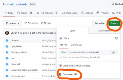
gihub-download-zip.jpg [ 70.56 KiB | Viewed 7723 times ]


If you use Git, you can ignore all the GitHub functionality entirely and just clone the URL directly (git clone https://github.com/vhelin/wla-dx), treating it like any other URL (GitHub, GitLab, static site, whatever) that provides a Git repo via HTTP. I mostly do this, though I do find the ability of GitHub/GitLab/etc. to let you link directly to a page showing a file fairly useful when I want to show someone a particular bit of code without making them download anything. (And the ZIP download option is of course also useful for those who don't use Git.)

It's worth remembering that GitHub is not Git, no more than your HTTP hosting service is Vim (or your editor of choice for HTML files). One of the reasons GitHub is so popular is that, if you use only Git and not the GitHub-specific features, it's trivial to put up a copy of your repo anywhere else if GitHub starts doing things you don't like. (And a lot of repos did quickly move from GitHub to GitLab when MS bought GitHub.)

_________________
Curt J. Sampson - github.com/0cjs


Top
 Profile  
Reply with quote  
PostPosted: Mon Jun 12, 2023 8:26 am 
Offline

Joined: Sat May 27, 2023 8:20 am
Posts: 9
Yuri wrote:
mark.williams wrote:
Perhaps your valid address decoding is allowing a clash on the data bus for when the UART is selected. I will have a look through your design and get back. Cheers Mark


Always open to a critical eye to make sure I didn't make a mistake anywhere, though I think BDD got it right with my mixing of logic families. Moving to HC parts settled most everything out. As for the weird interrupt issues, that seems to have calmed down.

I did figure out that I needed a pull up resistor on the 65C02's INT pin despite driving it with an IC. This was some head scratching on my part as the 65C02 datasheet doesn't seem to mention the open-drain nature of this pin, but the 65C22 docs seemed to suggest you should be using IC gates to drive the pin now and not the wire or with a diode (for performance reasons). But the interrupts weren't working until I added a pull up resistor; so it would seem I still need to wire or the logic?

Would be nice to get confirmation on that before I add more devices to the mix. Or when I switch to TTL which would let me use the 16550 which I think would be a nicer UART to use.

*shrug*


Top
 Profile  
Reply with quote  
PostPosted: Mon Jun 12, 2023 8:29 am 
Offline

Joined: Sat May 27, 2023 8:20 am
Posts: 9
The 6502 is meant to be pin compatible with the 6800. The IRQ on the 6800 is wired or to allow multiple devices to interrupt the processor. Hope this helps in the final revision. Mark


Top
 Profile  
Reply with quote  
PostPosted: Mon Jun 12, 2023 8:42 am 
Offline

Joined: Thu Mar 03, 2011 5:56 pm
Posts: 277
mark.williams wrote:
The 6502 is meant to be pin compatible with the 6800. The IRQ on the 6800 is wired or to allow multiple devices to interrupt the processor. Hope this helps in the final revision. Mark


6501, possibly?


Top
 Profile  
Reply with quote  
PostPosted: Mon Jun 12, 2023 12:40 pm 
Offline
User avatar

Joined: Sat Dec 01, 2018 1:53 pm
Posts: 727
Location: Tokyo, Japan
Yes, the 6501 was designed to be pin-compatible with the 6800. That's long gone now, but it's fair to say that the 65xx series uses essentially the same bus protocol as Motorola's 8-bit processors, and so yes, the IRQ line is designed to be used with a pull-up and multiple devices with open-collector outputs.

_________________
Curt J. Sampson - github.com/0cjs


Top
 Profile  
Reply with quote  
PostPosted: Mon Jun 12, 2023 1:29 pm 
Offline

Joined: Sat May 27, 2023 8:20 am
Posts: 9
Yes. I understabd the pin out changes that occured with the 6502 were to do with the clock circuitry and I assume the IRQ remained as wired or. NB The datasheets are silent on this :-( and (erroneously?) refer to them being driven by a std output.


Top
 Profile  
Reply with quote  
PostPosted: Mon Jun 12, 2023 1:51 pm 
Offline
User avatar

Joined: Sat Dec 01, 2018 1:53 pm
Posts: 727
Location: Tokyo, Japan
mark.williams wrote:
Yes. I understabd the pin out changes that occured with the 6502 were to do with the clock circuitry...

Not just that, but also the removal of tri-state ability on the address bus. (In fact, both changes made also by Motorola a couple of years later with the 6802.) And maybe a few other things.

Quote:
and I assume the IRQ remained as wired or.

The IRQ pin on the 6502 is not "wired-or" or not since it's an input. Any input can be used in a wired-or configuration or not, because that's about the configuration the outputs feeding it, not the input.

Quote:
NB The datasheets are silent on this :-( and (erroneously?) refer to them being driven by a std output.

Well, I wouldn't expect that an input would mention whether you're to drive it with totem-pole or open-collector, since normally you can do both, but the March 1980 datasheet even explicitly mentions open collector usage: "A 3KΩ external resistor should be used for proper wire-OR operation."

_________________
Curt J. Sampson - github.com/0cjs


Top
 Profile  
Reply with quote  
PostPosted: Mon Jun 12, 2023 5:22 pm 
Offline
User avatar

Joined: Thu May 28, 2009 9:46 pm
Posts: 8144
Location: Midwestern USA
mark.williams wrote:
Yes. I understabd the pin out changes that occured with the 6502 were to do with the clock circuitry and I assume the IRQ remained as wired or. NB The datasheets are silent on this :-( and (erroneously?) refer to them being driven by a std output.

The primary reason the 6501 pinout was changed was Motorola sued MOS Technology for patent infringement and as part of the settlement, the latter agreed to change the 6501 so it couldn't be plugged into an MC6800 board. The result was the “lawsuit-compatible” 6502.

All members of the 6502 family have been designed to use a wired-OR interrupt circuit, excepting WDC’s 65C22S, which has a totem-pole IRQ output and hence can’t be wired-OR without the use of a blocking diode. A better implementation has the 65C22S driving one of the inputs of an AND gate, and another input of the same gate wired-OR to the other interrupting devices in the system. The gate’s output drives the IRQB pin on the MPU—no pullup resistor required.

_________________
x86?  We ain't got no x86.  We don't NEED no stinking x86!


Top
 Profile  
Reply with quote  
Display posts from previous:  Sort by  
Post new topic Reply to topic  [ 62 posts ]  Go to page Previous  1, 2, 3, 4, 5  Next

All times are UTC


Who is online

Users browsing this forum: No registered users and 16 guests


You cannot post new topics in this forum
You cannot reply to topics in this forum
You cannot edit your posts in this forum
You cannot delete your posts in this forum
You cannot post attachments in this forum

Search for:
Jump to: