6502.org Forum  Projects  Code  Documents  Tools  Forum
It is currently Sat Apr 27, 2024 9:52 am

All times are UTC


Post new topic Reply to topic  [ 55 posts ]  Go to page Previous  1, 2, 3, 4
Author Message
PostPosted: Fri Jan 27, 2023 8:17 pm 
Offline

Joined: Mon Jan 09, 2023 9:33 pm
Posts: 23
I forgot about PowerUp for now. thanks reminds.


Top
 Profile  
Reply with quote  
PostPosted: Fri Jan 27, 2023 9:57 pm 
Offline
User avatar

Joined: Thu May 28, 2009 9:46 pm
Posts: 8144
Location: Midwestern USA
agsb wrote:
BigDumbDinosaur wrote:
agsb wrote:
Anyway, an alternative. Comments are full welcome :)

I can't read your schematic. Can you repost in monochrome?

Sorry, that is monochrome :) thanks your patience,

Some items of note:

  1. As kernelthread stated, your reset circuit will not toggle the reset line at power-on, which means your system won't boot until you hit the reset push button. This is a suitable circuit, as is this one (both are links to Garth’s website).

  2. As Garth noted, resistor R3 is unnecessary. The Schmitt inverter actively drives in both directions.

  3. Your clock circuit will work with NMOS and older CMS MPUs, but may not work with a WDC part. WDC specifies that the clock input to the MPU have a maximum rise/fall time of 5ns, which cannot be assured with 74HC logic. I recommend you use a 74AC14 (not a 74AHC14, whose output is more like 74HC) to produce a suitable clock pulse.

    That said, use of a can oscillator requires fewer parts and has the added bonus of being reliable. Roll-your-own, crystal-controlled clock circuits can be fickle, often due to uncontrolled parasitic capacitance, parts tolerances, ambient variances, etc. Can oscillator manufacturers have solved those problems and guarantee a stable output at the correct frequency as long as the oscillator is operated within the voltage, loading and temperature limits specified in the data sheet.

    At the low frequency at which you plan to run your system, connecting a can oscillator’s output directly to the MPU will work fine. Just keep the connection as short and direct as possible.

    At double-digit clock speeds beyond 12 MHz, I recommend you run the oscillator’s output through a D-type flip-flop (74AC74 is my preferred choice) to assure a symmetric clock signal with very sharp rise and fall. Most can oscillators have a symmetry tolerance that can be as much as 47/53, which may produce insidious timing violations if the clock speed is high enough. Use of the flop will eliminate that possibility. Note that the input frequency to the flop must be twice that of the desired Ø2 frequency.

    Attachment:
    File comment: Clock Generator
    clock_gen_2phase.GIF
    clock_gen_2phase.GIF [ 16.88 KiB | Viewed 6059 times ]

  4. Use of the clock to qualify chip selects, as you are doing with your RAM, is not ideal. In fact, there is no good reason to do so, as it is necessary to qualify the write cycle to any non-65xx peripheral with Ø2. Here’s an example of fully-qualified read/write logic that will work with either the 65C02 or 65C816. It’s a one-chip solution:

    Attachment:
    File comment: Fully-Qualified Read/Write
    read_write_qualify_alt.gif
    read_write_qualify_alt.gif [ 46.98 KiB | Viewed 6059 times ]

    The above shows use of a 74AC00, but a 74AHC00 is also a good choice, as is a 74HC00 if the clock rate isn't too high.

  5. Your decoding logic will select ROM any time the address is $8000 or higher, which is contrary to your memory map. On a read cycle, any address from $8000 to $8FFF will set the stage for major data bus contention between ROM and I/O.

  6. Your ROM address range from $9000 to $FFFF is 28K. Given that this is a 65C02 system, I'd be amazed if you used half of that. My POC V1.3 unit, which is 65C816-powered, has 12K of ROM, with a little more than 10K in use (which includes a full-features M/L monitor).

    A somewhat-more-granular decoding arrangement would open up more RAM space and still leave room for eight I/O devices, as well as plenty of ROM. For example:

    Attachment:
    File comment: 65C02 Glue Logic
    mapping_65c02.gif
    mapping_65c02.gif [ 41.26 KiB | Viewed 6059 times ]

    The above exposes 48K of RAM, 12K of ROM and 4K of I/O, with $C800-$CFFF being a mirror of $C000-$C7FF. A little extra logic could eliminate the mirroring and allow another eight I/O devices in the $C800-$CFFF range. Also illustrated is the qualified read/write logic for use with RAM, ROM and non-65xx peripherals (bottom of drawing).

    While use of 74AC logic is illustrated, 74HC will be reliable up to about 8 MHz, and 74AHC preferred above that threshold.

Speaking of peripherals, chip selects and RWB must be valid for 65xx devices prior to the rise of Ø2. Devices such as the 65C22 and 65C51 “understand” the 65C02 bus cycle and need no clock qualification, since they have Ø2 inputs. Not observing this requirement will result in the device failing to respond when addressed.

Also, note that WDC produces two forms of the 65C22: W65C22N and W65C22S. The former has an open-collector IRQ output, whereas the latter has a totem-pole IRQ output. You can wire-OR a 65C22N into your IRQ circuit, but not so with the 65C22S.

_________________
x86?  We ain't got no x86.  We don't NEED no stinking x86!


Top
 Profile  
Reply with quote  
PostPosted: Sun Feb 12, 2023 1:43 am 
Offline

Joined: Mon Jan 09, 2023 9:33 pm
Posts: 23
Thanks for insigths.

My first build will be a MOS6502/2x6522/1x6551/AT28C256/HM62256 at half of 1.8543 Mhz, and a minimal BIOS for USART, Monitor and Forth, just for learn


Top
 Profile  
Reply with quote  
PostPosted: Sat Mar 11, 2023 9:14 pm 
Offline

Joined: Sat Oct 09, 2021 11:21 am
Posts: 703
Location: Texas
Interesting! Ben Eater just came out with a new video, and look here (link timed to 17:08):

https://youtu.be/oLYLnb7kpLg?t=1028

He resets the computer, sending an asterisk. But then he starts pushing the reset button manually. He pushed the reset button 4 times. He *should* have got 4 asterisks, but instead he got 10 asterisks. Duplicates, because his reset circuit bounces.

Well, there's proof enough. If you want it bouncing, go ahead with a simple RC circuit. If you want it to be done properly, use a dedicated IC such as the DS1813.

That's all, thanks!

Chad


Top
 Profile  
Reply with quote  
PostPosted: Sun Mar 12, 2023 5:27 am 
Offline
User avatar

Joined: Thu May 28, 2009 9:46 pm
Posts: 8144
Location: Midwestern USA
sburrow wrote:
Interesting! Ben Eater just came out with a new video, and look here (link timed to 17:08):

https://youtu.be/oLYLnb7kpLg?t=1028

He resets the computer, sending an asterisk. But then he starts pushing the reset button manually. He pushed the reset button 4 times. He *should* have got 4 asterisks, but instead he got 10 asterisks. Duplicates, because his reset circuit bounces.

Yep! I saw that. Problem is he doesn’t say anything about it, which means the naive viewer of his video who is trying to get his 6502 unit running isn’t going to understand the implications of what we saw.

_________________
x86?  We ain't got no x86.  We don't NEED no stinking x86!


Top
 Profile  
Reply with quote  
PostPosted: Sun Mar 12, 2023 2:42 pm 
Offline

Joined: Sat Feb 19, 2022 10:14 pm
Posts: 147
I saw that too. You can hear him pause just slightly at that point as if he's wondering whether to explain it or not.

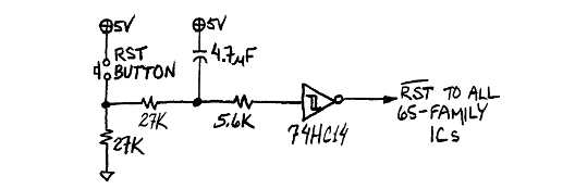
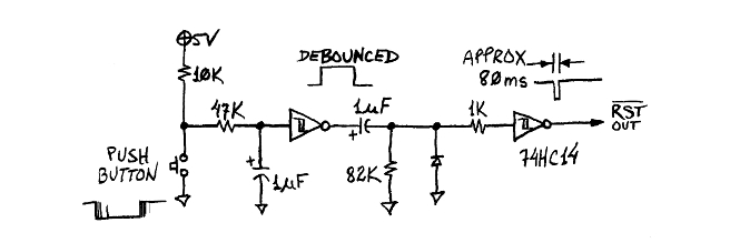
If you look closely at the build in the video, you'll see that the reset circuit doesn't have a capacitor, even though it's there in the photo and schematic on his website. It's also on the photo on the kit box. There are other components as well in the photo and schematic not covered in his videos. He's clearly left things open for future development and more videos. Making videos is part of his business model. Based on his Patreon membership he's making at least $1500 per video and likely a lot more. He even says in his FAQ in response to a question about adding a certain feature to a project: "If I did, I'd want to make videos about it."

Interestingly, the RDY pin in his video is tied directly to 5 volts while in the kit photo and schematic it's tied through a resistor. I noted this a few days ago when reading what BDD said in another thread:
BDD wrote:
You cannot connect RDY directly to VCC. That was also pointed out to you many posts ago. RDY is a bi-directional signal and will be driven low in the event the MPU executes a WAI instruction, whether intentional or not. The way you have it would result in the MPU trying to short out the power supply. Use a 3.3K pullup resistor on RDY.
I was aware of this functionality but hadn't fully considered it. I had played with the WAI instruction a few times but could never get it to work. On reading BDD's comment, things clicked. I had tied the RDY pin directly to 5 volts as I had for all of my builds since my first Ben Eater kit!

That's one of the problems with kits based on videos. Unless the series is complete, you'll likely move ahead faster than the series. Ben's just started on serial, but I've long since added it to my other builds and had added a PS/2 keyboard long before Ben got around to it. I still have my original Ben Eater build though so I can follow along as he adds more videos.

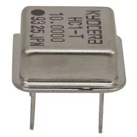
On a side note, I see that Ben's kits have new packaging. It looks like he's found a new producer for these. Also, his kits are no longer available at Jameco here in the US.


Top
 Profile  
Reply with quote  
PostPosted: Mon Mar 13, 2023 6:30 pm 
Offline
User avatar

Joined: Tue Feb 28, 2023 11:39 pm
Posts: 133
Location: Texas
tmr4 wrote:
Interestingly, the RDY pin in his video is tied directly to 5 volts while in the kit photo and schematic it's tied through a resistor. I noted this a few days ago when reading what BDD said in another thread:
BDD wrote:
You cannot connect RDY directly to VCC. That was also pointed out to you many posts ago. RDY is a bi-directional signal and will be driven low in the event the MPU executes a WAI instruction, whether intentional or not. The way you have it would result in the MPU trying to short out the power supply. Use a 3.3K pullup resistor on RDY.
I was aware of this functionality but hadn't fully considered it. I had played with the WAI instruction a few times but could never get it to work. On reading BDD's comment, things clicked. I had tied the RDY pin directly to 5 volts as I had for all of my builds since my first Ben Eater kit!


I should have paid more attention to the datasheet.... :(

I fixed that, it's on a 3.3K right now, even though there's nothing else connected to it on my breadboard. I also hadn't really messed with interrupts yet, though I was getting around to it.

I'll be sure to run the others through a resistor pack once I get a PCB designed.


Top
 Profile  
Reply with quote  
PostPosted: Sat May 06, 2023 11:55 pm 
Offline

Joined: Sat Oct 09, 2021 11:21 am
Posts: 703
Location: Texas
Here's *another* instance of the bouncing reset circuit, and the effects.

https://youtu.be/CnA8nG3zYHw?t=1391

He claims he "double tapped". I know this wasn't the point of the video, but you can see the effects clearly. It starts sending data, then stops, starts up again, and finally finishes cleanly.

I believe I only see that 1K pull-up resistor on the reset line here, I don't think I see the 0.1uF cap here.

Just another observation!

Chad


Top
 Profile  
Reply with quote  
PostPosted: Sun May 07, 2023 11:30 am 
Offline
User avatar

Joined: Thu May 28, 2009 9:46 pm
Posts: 8144
Location: Midwestern USA
sburrow wrote:
Here's *another* instance of the bouncing reset circuit, and the effects.

https://youtu.be/CnA8nG3zYHw?t=1391

He claims he "double tapped". I know this wasn't the point of the video, but you can see the effects clearly. It starts sending data, then stops, starts up again, and finally finishes cleanly.

I believe I only see that 1K pull-up resistor on the reset line here, I don't think I see the 0.1uF cap here.

Just another observation!

Chad

Ah, yes. Never underestimate the power of the Internet to misinform. :D

_________________
x86?  We ain't got no x86.  We don't NEED no stinking x86!


Top
 Profile  
Reply with quote  
PostPosted: Sun Jun 04, 2023 8:53 pm 
Offline

Joined: Sat Oct 09, 2021 11:21 am
Posts: 703
Location: Texas
Ok, this really will be the last time I comment on this. Here in the latest video:

https://youtu.be/HlLCtjJzHVI?t=559

He admits that he "needs to debounce that reset circuit". Whelp, that's better than making excuses.

That's all, thanks!

Chad


Top
 Profile  
Reply with quote  
Display posts from previous:  Sort by  
Post new topic Reply to topic  [ 55 posts ]  Go to page Previous  1, 2, 3, 4

All times are UTC


Who is online

Users browsing this forum: No registered users and 13 guests


You cannot post new topics in this forum
You cannot reply to topics in this forum
You cannot edit your posts in this forum
You cannot delete your posts in this forum
You cannot post attachments in this forum

Search for:
Jump to: