6502.org Forum  Projects  Code  Documents  Tools  Forum
It is currently Thu May 09, 2024 2:21 pm

All times are UTC


Post new topic Reply to topic  [ 13 posts ] 
Author Message
PostPosted: Tue Dec 21, 2021 3:51 pm 
Offline
User avatar

Joined: Sun Nov 07, 2021 4:11 pm
Posts: 101
Location: Toronto, Canada
Howdy! I'm trying to use a 74HC574 to hold on to some data bits that should only be visible when the clock is on the low part of the duty cycle (because something else will be on the bus during the high part). I thought I could use the O̅E̅ line for this purpose and simply connect it to the clock line, so that, when the clock is high, the '574 simply disconnects itself from the bus, but somehow I can't get the chip to behave the way I want… when an input is high, the output just stays high all the time.

With an input set high, if I manually connect O̅E̅ to either VCC or ground, I can see the output change, but if I attach any kind of clock signal, no matter how slow (I went all the way down to ~10kHz), the output is always high, rather than following the clock.

I've wired things like this—the diagram on the left is just the oscillator and the '574, while the one on the right includes a 4040 to divide the clock down to slower speeds:

Image

Not quite sure where I'm going wrong… I tried looking at the signal with my 'scope, and everything looks reasonable to me; if anyone has any suggestions, I'd welcome them. Cheers!


Attachments:
Screen Shot 2021-12-21 at 10.47.48.png
Screen Shot 2021-12-21 at 10.47.48.png [ 124.29 KiB | Viewed 1673 times ]
Top
 Profile  
Reply with quote  
PostPosted: Tue Dec 21, 2021 7:07 pm 
Offline

Joined: Sat Oct 09, 2021 11:21 am
Posts: 704
Location: Texas
Might I be the first to reply? I'm still a newbie, but I've used the '4040 before.

MR (master reset) on the '4040 is high enabled. On your diagram, you have it connected to +5V, thus it's ALWAYS in reset mode, thus the output of the '4040 is always a low.

https://assets.nexperia.com/documents/d ... CT4040.pdf

At least that's my guess?

Chad


Top
 Profile  
Reply with quote  
PostPosted: Tue Dec 21, 2021 7:30 pm 
Offline
User avatar

Joined: Fri Aug 30, 2002 1:09 am
Posts: 8432
Location: Southern California
With CMOS circuits, when you disable the outputs and nothing else is driving those lines from another source, the capacitance in the board, sockets, 'scope probe, etc. will hold the last value for a long time, even milliseconds (not just microseconds or nanoseconds), according to something I observed by accident when I was developing the test for my 4Mx8 SRAM modules. (This is why you don't have to worry about violating the 65c02's hold times on a read operation after phase 2 falls. The data will be held until something else drives the bus.) I did not try to see how much longer I could go. It was just an interesting observation that was not really related to what I was working on.

_________________
http://WilsonMinesCo.com/ lots of 6502 resources
The "second front page" is http://wilsonminesco.com/links.html .
What's an additional VIA among friends, anyhow?


Top
 Profile  
Reply with quote  
PostPosted: Tue Dec 21, 2021 8:14 pm 
Offline
User avatar

Joined: Sun Nov 07, 2021 4:11 pm
Posts: 101
Location: Toronto, Canada
sburrow wrote:
Might I be the first to reply? I'm still a newbie, but I've used the '4040 before.

MR (master reset) on the '4040 is high enabled. On your diagram, you have it connected to +5V, thus it's ALWAYS in reset mode, thus the output of the '4040 is always a low.

https://assets.nexperia.com/documents/d ... CT4040.pdf

At least that's my guess?

Chad


Thanks Chad—that's a mistake in a hastily-assembled diagram, but good catch. The same problem happens on the left side, where there is no divider anyway, unfortunately.


Top
 Profile  
Reply with quote  
PostPosted: Tue Dec 21, 2021 8:19 pm 
Offline
User avatar

Joined: Sun Nov 07, 2021 4:11 pm
Posts: 101
Location: Toronto, Canada
GARTHWILSON wrote:
With CMOS circuits, when you disable the outputs and nothing else is driving those lines from another source, the capacitance in the board, sockets, 'scope probe, etc. will hold the last value for a long time, even milliseconds (not just microseconds or nanoseconds), according to something I observed by accident when I was developing the test for my 4Mx8 SRAM modules. (This is why you don't have to worry about violating the 65c02's hold times on a read operation after phase 2 falls. The data will be held until something else drives the bus.) I did not try to see how much longer I could go. It was just an interesting observation that was not really related to what I was working on.


Thanks, Garth. I actually observed something similar when experimenting—the line would decay very slowly while the bus wasn't being driven, and then get picked up again to 5V when the next cycle came along. I think I'm just using the wrong tool for the job—perhaps, the right way to go about it is to use the '574 as a latch, ignoring the OE line, and then put a bus transceiver like a '245 between it and the bus… I was hoping for once the solution wasn't going to be “more ICs” :-)


Top
 Profile  
Reply with quote  
PostPosted: Tue Dec 21, 2021 9:12 pm 
Offline
User avatar

Joined: Fri Dec 11, 2009 3:50 pm
Posts: 3354
Location: Ontario, Canada
Quote:
I'm trying to use a 74HC574 to hold on to some data bits that should only be visible when the clock is on the low part of the duty cycle (because something else will be on the bus during the high part).
CountChocula, is it the data bus of a microprocessor that you intend to connect to? Please explain what it is you're up to.

Quote:
I was hoping for once the solution wasn't going to be “more ICs”
In case it helps, this diagram shows the internals of a '574. Notice that storing a value is a separate, independent function from turning on and off the output. I don't think you will need more ICs (but I'm not entirely clear on what it is you're up to).

-- Jeff


Attachments:
574 detail.png
574 detail.png [ 4.52 KiB | Viewed 1634 times ]

_________________
In 1988 my 65C02 got six new registers and 44 new full-speed instructions!
https://laughtonelectronics.com/Arcana/ ... mmary.html
Top
 Profile  
Reply with quote  
PostPosted: Tue Dec 21, 2021 9:43 pm 
Offline
User avatar

Joined: Sun Nov 07, 2021 4:11 pm
Posts: 101
Location: Toronto, Canada
Dr Jefyll wrote:
Quote:
I'm trying to use a 74HC574 to hold on to some data bits that should only be visible when the clock is on the low part of the duty cycle (because something else will be on the bus during the high part).
CountChocula, is it the data bus of a microprocessor that you intend to connect to? Please explain what it is you're up to.


Hey Jeff—I am trying to build a VGA interface for my SBC. So far, I have built the “video” side of the interface, which has its own memory chip and seems to work (at least in the sense that I see a stable image on my monitor—it shows garbage, and I'm hoping it's the garbage that's in the RAM :-) ).

Now I need to build the “CPU” side of the thing that allows the computer to write in the RAM. Since the interface has its own internal clock, my thought was to set up 4 registers using '574 latches (19 bits of addresses, plus 8 bits of data) whose inputs are connected to the CPU bus, and outputs to the memory chip; then, I can tie the latches' OE lines to the video interface's clock signal, so that when the clock is low (at which point the counter that scans the memory to feed pixels into the output will be disabled—I already built that part), the latches will be able to access the RAM.

Quote:
I was hoping for once the solution wasn't going to be “more ICs”
In case it helps, this diagram shows the internals of a '574. Notice that storing a value is a separate, independent function from turning on and off the output. I don't think you will need more ICs (but I'm not entirely clear on what it is you're up to).

That diagram makes sense to me; if I'm reading it correctly, it implies that the OE line is asynchronous, which means that things should work, but… they don't. No matter how simple or slow I make the circuit (at least down to a few kHz), the output of the '574 seems to ignore the OE line altogether—though I will say that it works if I connect it by hand to ground or 5V. Maybe it's just really slow, like Garth was suggesting, because I have wired things too naïvely?

Thanks again!


Top
 Profile  
Reply with quote  
PostPosted: Tue Dec 21, 2021 9:57 pm 
Offline
User avatar

Joined: Fri Aug 30, 2002 1:09 am
Posts: 8432
Location: Southern California
CountChocula wrote:
Maybe it's just really slow, like Garth was suggesting, because I have wired things too naïvely?

Let's see if I can clarify this. I was not suggesting the circuit is slow. It's just that when you turn off the output and nothing else is driving the line, the capacitance, even if only 10pF, acts as a sample-and-hold circuit. In fact, that's how sample-and-hold circuits work for analog-to-digital converters. See https://en.wikipedia.org/wiki/Sample_and_hold . The gate is held open while you're tracking an analog input voltage, and when you want to covert it to a digital number, you freeze it at the instant you want, so that that value is held while the analog-to-digital converter is working on the conversion, since it needs that input to be stable until it's done.

_________________
http://WilsonMinesCo.com/ lots of 6502 resources
The "second front page" is http://wilsonminesco.com/links.html .
What's an additional VIA among friends, anyhow?


Top
 Profile  
Reply with quote  
PostPosted: Tue Dec 21, 2021 10:02 pm 
Offline

Joined: Sat Oct 09, 2021 11:21 am
Posts: 704
Location: Texas
CountChocula wrote:
That diagram makes sense to me; if I'm reading it correctly, it implies that the OE line is asynchronous, which means that things should work, but… they don't. No matter how simple or slow I make the circuit (at least down to a few kHz), the output of the '574 seems to ignore the OE line altogether—though I will say that it works if I connect it by hand to ground or 5V. Maybe it's just really slow, like Garth was suggesting, because I have wired things too naïvely?


I think, but might be wrong, that Jeff is saying that OE doesn't actually store data. It just allows it to pass through from the flip-flop onto the output pins. IDK though.

One thing I found on my first build was that "if it's not working every time, it's not working at all". I *knew* my board was working... sometimes. But really, that was just not the case. It was sporadic and faulty because I had wired something wrong. In the end, even if it's working... sometimes, that could actually mean it doesn't work at all. It's something I use in my mind to not assume anything.

Glad your VGA portion is up and running! That's the scary part for me. Since I'm using the Dual Port SRAM, I guess I've circumvented the issue you are currently having (at huge costs by the way). I like the idea of using the latches though, that's the style I used on my EEPROM programmer.

Thanks.

Chad


Top
 Profile  
Reply with quote  
PostPosted: Tue Dec 21, 2021 10:05 pm 
Offline
User avatar

Joined: Fri Dec 11, 2009 3:50 pm
Posts: 3354
Location: Ontario, Canada
CountChocula wrote:
which means that things should work, but… they don't
A misunderstanding, perhaps. Things may "click" for you if you try the following. Choose one of the '574 outputs and connect it to two resistors, one going to ground and one to Vcc. Value not critical -- 2K to 100K, say (but both resistors the same). Nothing else (except your meter/scope) connected.

You'll see either a high or a low (depending what's stored in the FF) when the output is enabled (/OE low). But when the output is disabled the chip will cease to drive, and the resistors will bring the voltage to one-half of Vcc (overcoming whatever capacitance is present).

Glad to hear about the project. And your SBC uses a 65C02, is that right?

-- Jeff

_________________
In 1988 my 65C02 got six new registers and 44 new full-speed instructions!
https://laughtonelectronics.com/Arcana/ ... mmary.html


Top
 Profile  
Reply with quote  
PostPosted: Wed Dec 22, 2021 1:14 am 
Offline
User avatar

Joined: Sun Nov 07, 2021 4:11 pm
Posts: 101
Location: Toronto, Canada
sburrow wrote:
CountChocula wrote:
One thing I found on my first build was that "if it's not working every time, it's not working at all". I *knew* my board was working... sometimes. But really, that was just not the case. It was sporadic and faulty because I had wired something wrong. In the end, even if it's working... sometimes, that could actually mean it doesn't work at all. It's something I use in my mind to not assume anything.


Amen!

Quote:
Glad your VGA portion is up and running! That's the scary part for me. Since I'm using the Dual Port SRAM, I guess I've circumvented the issue you are currently having (at huge costs by the way). I like the idea of using the latches though, that's the style I used on my EEPROM programmer.


Thanks! As I told my friend a couple days ago, I've never been happier to see garbage on a screen :-)

Image


Attachments:
Untitled.jpg
Untitled.jpg [ 368.56 KiB | Viewed 1604 times ]
Top
 Profile  
Reply with quote  
PostPosted: Wed Dec 22, 2021 1:27 am 
Offline
User avatar

Joined: Sun Nov 07, 2021 4:11 pm
Posts: 101
Location: Toronto, Canada
Dr Jefyll wrote:
CountChocula wrote:
which means that things should work, but… they don't
A misunderstanding, perhaps. Things may "click" for you if you try the following. Choose one of the '574 outputs and connect it to two resistors, one going to ground and one to Vcc. Value not critical -- 2K to 100K, say (but both resistors the same). Nothing else (except your meter/scope) connected.

You'll see either a high or a low (depending what's stored in the FF) when the output is enabled (/OE low). But when the output is disabled the chip will cease to drive, and the resistors will bring the voltage to one-half of Vcc (overcoming whatever capacitance is present).


Thanks Jeff—it did click… after sending my last message, I re-read Garth's and had the intuition to add a pull-down resistor to the output, and sure enough things started working the way I expected. This makes complete sense, of course; not sure what I was thinking! I'm going to try wiring a couple '574s to see if I can at least write to the first few rows of pixels.

Quote:
Glad to hear about the project. And your SBC uses a 65C02, is that right?


Thank you, yes! About three months ago, I got it in my head to build an SBC from scratch; with zero experience, it's been quite the learning curve, but I already have a prototype of the computer on a pcb:

Image

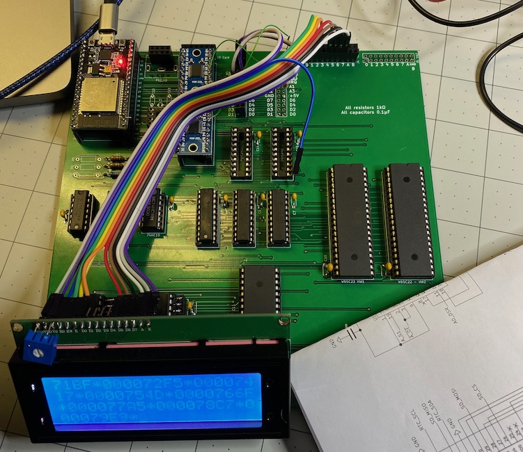
It works great all the way up to 13MHz, and so I wanted to get a video interface done (and fix a few bugs… notice the PS/2 connector placed backwards on the PCB in the top-left corner) before bootstrapping a simple OS. To me, a computer doesn't feel like a computer without a screen :-)

This video interface has proven to be quite the pickle; building the computing unit, by comparison, was a lot simpler (thanks in no small part to all the resources on this board and Garth's primer). I was dreading getting to this part, and so far it's been kicking my butt. Lots of learning, though, so that's great!

Thanks again to all of you for all your help!


Attachments:
Untitled.jpg
Untitled.jpg [ 235.55 KiB | Viewed 1603 times ]
Top
 Profile  
Reply with quote  
PostPosted: Wed Dec 22, 2021 2:13 am 
Offline

Joined: Sat Oct 09, 2021 11:21 am
Posts: 704
Location: Texas
CountChocula wrote:
Thanks Jeff—it did click… after sending my last message, I re-read Garth's and had the intuition to add a pull-down resistor to the output, and sure enough things started working the way I expected. This makes complete sense, of course; not sure what I was thinking! I'm going to try wiring a couple '574s to see if I can at least write to the first few rows of pixels.


Very good news! And I love that pic of "garbage", beautiful indeed :) I went back and looked at why you'd want a pull-down resistor, and I also now see why that's important. I need to learn too! Thanks.

Chad


Top
 Profile  
Reply with quote  
Display posts from previous:  Sort by  
Post new topic Reply to topic  [ 13 posts ] 

All times are UTC


Who is online

Users browsing this forum: No registered users and 4 guests


You cannot post new topics in this forum
You cannot reply to topics in this forum
You cannot edit your posts in this forum
You cannot delete your posts in this forum
You cannot post attachments in this forum

Search for:
Jump to: