(The circuit also includes a .1µF decoupling cap, not pictured; also my can's datasheet says that Pin 1 should be NC.)
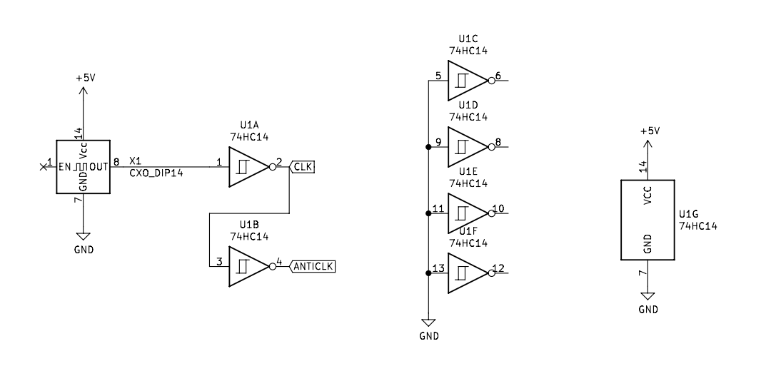
I'm seeing some really strange results that I don't understand on the 'scope. This is the input signal coming from the oscillator, as seen on Pin 1 of the '14 chip:
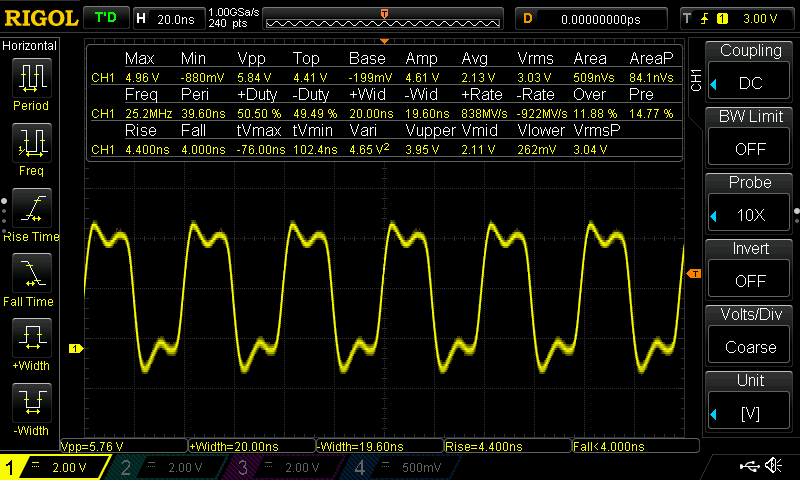
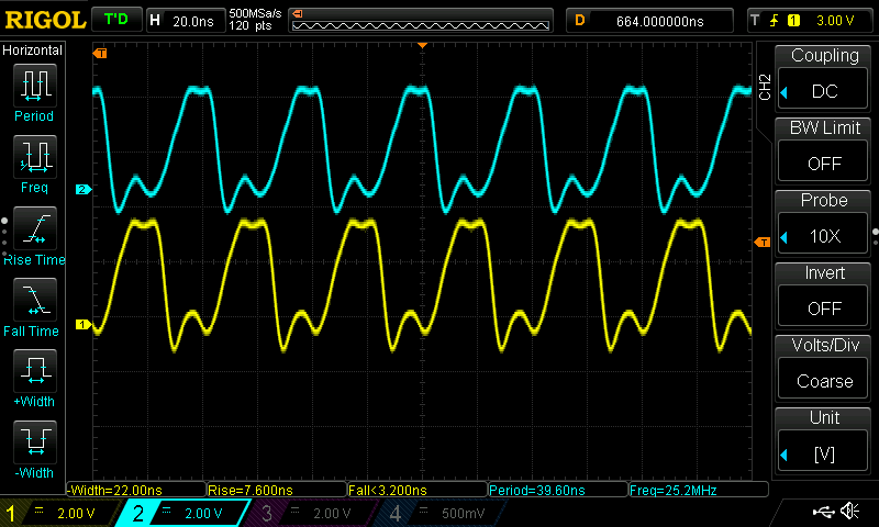
And this is what comes out on Pin 2:
I'm… pretty baffled; I expected a relatively nice square wave to show up on Pin 2, and this looks like anything but. I've swapped out both the oscillator and the IC, with no change. FWIW, this is currently on a breadboard—not sure if it could be problematic for something this simple.
Once again, I feel like I'm missing something obvious, and would be grateful for any guidance
Thanks!
Datasheets: ECS-100A oscillator and 74HCT14 (apologies for the links; for some reason, I can't seem to be able to upload files right now).