6502.org Forum  Projects  Code  Documents  Tools  Forum
It is currently Sun Apr 28, 2024 10:03 pm

All times are UTC


Post new topic Reply to topic  [ 163 posts ]  Go to page Previous  1, 2, 3, 4, 5, 6 ... 11  Next
Author Message
PostPosted: Wed Oct 13, 2021 1:11 pm 
Offline
User avatar

Joined: Tue Mar 05, 2013 4:31 am
Posts: 1373
Hmmm, the Vic-20 comes to mind. Commodore used the NMI driven by the second 6522 timer for timing. A fair amount of source code and not a very fast baud rate. I'd skip it and use a real UART. Just my $0.02.

_________________
Regards, KM
https://github.com/floobydust


Top
 Profile  
Reply with quote  
PostPosted: Wed Oct 13, 2021 1:30 pm 
Offline

Joined: Sat Oct 09, 2021 11:21 am
Posts: 703
Location: Texas
Dr Jefyll wrote:
That means the CPU will be unable to do anything else during the time it's transmitting a character, or listening to see if there's a character to receive.


By the way, yes, that does sound like a good tradeoff to me. So, "cannot do anything while listening" is interesting. An idea I was thinking is that I could set up some type of an interrupt on the start bit. How would I then NOT trigger an interrupt every 'low' bit I do not yet know, but just thinking here. Still, if I put the computer into a 'listen for some serial data' loop, hit 'enter' on my computer, then it should not have any problems.

Thank you for that reply!


Top
 Profile  
Reply with quote  
PostPosted: Wed Oct 13, 2021 1:35 pm 
Offline

Joined: Sat Oct 09, 2021 11:21 am
Posts: 703
Location: Texas
floobydust wrote:
Commodore used the NMI driven by the second 6522 timer for timing.


Now THAT is an interesting idea. Hm, will be thinking about that, thank you.

I accept your $0.02. I'm not ignoring it, just thinking through all the possibilities and limitations at once. Mostly, I'm learning.

[ I know we are all probably similar in how we think, that's who we are, and why you find folks like us on 6502.org at all. I'm one to think of every single possibility, every single instance. Map it all out in the mind. Have an answer for every question, whether it actually gets asked or not. I am a math professor, I get paid to do this sort of thing. Turn probabilities into possibilities. ]

Thank you!


Top
 Profile  
Reply with quote  
PostPosted: Wed Oct 13, 2021 2:27 pm 
Offline
User avatar

Joined: Fri Dec 11, 2009 3:50 pm
Posts: 3349
Location: Ontario, Canada
sburrow wrote:
An idea I was thinking is that I could set up some type of an interrupt on the start bit.
That approach is workable if you're not concerned about being able to receive and transmit simultaneously (ie, Full Duplex). Maybe that capability isn't required.

But if Full Duplex is the goal -- and assuming you only have one timer and interrupt line available (not one of each for transmit and one of each for receive) -- I'd suggest having a periodic interrupt that runs continuously whenever either or both task(s) is active. (For the sake of simpler code, it may even be reasonable to let the periodic interrupts continue even when neither the transmit task nor the receive task is active.)

You'll probably want the interrupts to occur at triple ( 3x ) the bit rate, because doing so allows you to start receiving a character at any time (meaning, on any given interrupt). Remember, you don't get to choose when an incoming character will arrive. You could be in the midst of transmitting a character, then suddenly need to also start receiving a character. And of course it's unlikely that the bit-clock of the incoming character will be time-aligned with that of the outgoing character. But having interrupts at a 3x rate means the receive and transmit tasks can be phase shifted by zero, by 1/3, or by 2/3 of a bit-time relative to one another.


So! With the scheme I propose, if there's a character in the process of being transmitted then the Interrupt Service Routine will, on every third interrupt, shift out a bit onto the TxD output. And, if there's a character in the process of being received then the ISR will, on every third interrupt, shift in a bit from the RxD input.

To minimize the performance impact, the ISR needs to do the absolute minimum then exit as soon as possible. (After all, there'll be a foreground task that can manage the big picture.) One way to keep the ISR fast is to have it begin with an indirect jump (or, use self-modifying code) that gets updated according to what's going on. This'll be faster than having the ISR read various activity status bits then do conditional branches.

-- Jeff

Edits: improved explanation, and this PS. Further edit: fix diagram

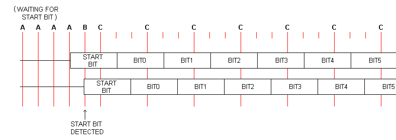
Here's a diagram to explain the choice of a 3x interrupt rate, as opposed to 2x or 4x or any other number.
Attachment:
3x timing for asynch.png
3x timing for asynch.png [ 3.38 KiB | Viewed 5448 times ]
The vertical red lines indicate interrupts, and sooner or later the incoming character will be detected. This entails a degree of variability, and the upper and lower depictions of the incoming character illustrate the boundaries of that variability.

At "B," the Start Bit is detected. Then at "C" a repetitive pattern begins. There'll be an interrupt that samples RxD, one that does nothing, another that does nothing, then the pattern repeats until all bits have been received. You'll notice that the "sample RxD" interrupts remain well centered within the bit-time (between 33% and 66%), as desired.

_________________
In 1988 my 65C02 got six new registers and 44 new full-speed instructions!
https://laughtonelectronics.com/Arcana/ ... mmary.html


Last edited by Dr Jefyll on Thu Oct 14, 2021 2:30 pm, edited 3 times in total.

Top
 Profile  
Reply with quote  
PostPosted: Wed Oct 13, 2021 2:39 pm 
Offline

Joined: Tue Sep 03, 2002 12:58 pm
Posts: 293
Another option is to skip the UART altogether and use something like the FT240 or FT245. I haven't used one myself, but it looks like it pretends to be a serial port on the PC side, and gives you a simple parallel interface on the other end.


Top
 Profile  
Reply with quote  
PostPosted: Wed Oct 13, 2021 5:19 pm 
Offline
User avatar

Joined: Thu May 28, 2009 9:46 pm
Posts: 8153
Location: Midwestern USA
floobydust wrote:
Hmmm, the Vic-20 comes to mind. Commodore used the NMI driven by the second 6522 timer for timing. A fair amount of source code and not a very fast baud rate. I'd skip it and use a real UART. Just my $0.02.

The same was done in the C-64 and C-128, using the second 6526 and NMIs. There are a lot of problems with getting bit-banged TIA-232 to run at any significant speed and without errors—the C-64 and C-128 renditions are also hobbled by a hardware bug found in many 6526s.

Given that UARTs are a dime a dozen these days and lots of working code exists to use one, I fail to see any incentive to bit-bang TIA-232. Once again, I must caution about becoming overly complex on a first-ever design. This is exactly the sort of thing I would be avoiding.

_________________
x86?  We ain't got no x86.  We don't NEED no stinking x86!


Top
 Profile  
Reply with quote  
PostPosted: Wed Oct 13, 2021 5:30 pm 
Offline

Joined: Sat Oct 09, 2021 11:21 am
Posts: 703
Location: Texas
John West wrote:
Another option is to skip the UART altogether and use something like the FT240 or FT245.


Well! That is a good idea! I don't know much about it, but I'll have to research it. Thank you for that option!


Top
 Profile  
Reply with quote  
PostPosted: Wed Oct 13, 2021 5:33 pm 
Offline

Joined: Sat Oct 09, 2021 11:21 am
Posts: 703
Location: Texas
BigDumbDinosaur wrote:
Once again, I must caution about becoming overly complex on a first-ever design. This is exactly the sort of thing I would be avoiding.


Indeed. Thank you BDD.

I bought one of those adapters just now on Amazon for $6. I'm going to test it out on a Raspberry Pi, using delays and whatnot to emulate the oscillator as best as I can. If I'm not happy, "turn around don't drown". Before I even get a PCB I'm going to put the whole thing together on a couple of breadboards. Or at least large sections of it.

Thank you, yes, I will be cautious, and your concern is something I am not brushing off.


Top
 Profile  
Reply with quote  
PostPosted: Thu Oct 14, 2021 9:08 am 
Offline
User avatar

Joined: Thu Dec 11, 2008 1:28 pm
Posts: 10793
Location: England
sburrow wrote:
This is an excerpt from Garth's RS-232 Primer page:

"...(There is a forum topic here on bit-banging 57,600bps on a 1MHz 6502.) ... "

http://wilsonminesco.com/RS-232/RS-232primer.html


Just to help a bit, I've linkified it:
Quote:
"...(There is a forum topic here on bit-banging 57,600bps on a 1MHz 6502.) ... "


This feat of ingenuity is a similar effective rate to the UPURS project for Acorn's BBC Micro, where the 6502 runs mostly at 2MHz but slows to 1MHz for I/O access. This project achieves 115,200 bps. There's a megathread in which it was developed.


Top
 Profile  
Reply with quote  
PostPosted: Thu Oct 14, 2021 10:16 am 
Offline
User avatar

Joined: Wed Feb 13, 2013 1:38 pm
Posts: 586
Location: Michigan, USA
Dr Jefyll wrote:
sburrow wrote:
... You'll probably want the interrupts to occur at triple ( 3x ) the bit rate, because doing so allows you to start receiving a character at any time (meaning, on any given interrupt)

I used a similar method several years ago for a PIC demo (posted on PICLIST) and it worked quite well. The PIC was running at 2 MIPS which is quite a bit faster than a 2 or 4 MHz 65C02...

Code:
;******************************************************************
;                                                                 *
;   Filename: 12F683 Full-Duplex 9600 Demo.asm                    *
;     Author: Mike McLaren, K8LH                                  *
;       Date: 02-Jun-05  (last revision 04-Dec-05)                *
;                                                                 *
;    Full Duplex Bit-Banged 9600 Baud Serial I/O Demo             *
;                                                                 *
;   ·Uses 12F683 INTOSC running at 8-MHz                          *
;   ·Bit rate error 0.6% plus or minus 1.0% for INTOSC            *
;   ·Bit-banged 9600 baud serial I/O                              *
;     ·Full Duplex (TX and RX simultaneously)                     *
;     ·Interrupts at approximately 3X bit rate every              *
;      34.5 usecs (every 69 instruction cycles)                   *
;     ·Circular 16-byte RX character buffer                       *
;     ·Circular 16-byte TX character buffer                       *
;     ·Inverted TX and RX signals (MAX232A or similar             *
;      inverting RS-232 interface required)                       *
;   ·ISR and support routines Init232, Put232, and Get232         *
;    fit comfortably in the first 189 words of code space         *
;    occupying memory from 0x04 through 0xBC (185 words)          *
;                                                                 *
;      MPLab: 7.21    (tabs=8)                                    *
;      MPAsm: 4.02                                                *
;                                                                 *
;******************************************************************
Code:
;******************************************************************
;                                                                 *
;     Interrupt Service Routine for a Full Duplex Bit-Banged      *
;     9600 Baud Serial I/O with 16 byte circular receive and      *
;     transmit buffers...                                         *
;                                                                 *
;     Interrupts are generated at approximately 3 times the       *
;     bit rate for 9600 baud at 34.5-usec intervals or every      *
;     69 instruction cycles.                                      *
;                                                                 *
;     The transmit and receive processes are executed in the      *
;     correct sequence each interrupt cycle by using a state      *
;     machine variable and jump table for both RX and TX.         *
;                                                                 *
;     After detecting a start bit, the receive bit stream is      *
;     sampled every third interrupt cycle in the approximate      *
;     middle third of each bit (between 33% and 66%).             *
;                                                                 *
;     The 16 byte circular TXBUFF is located at B0..BF in RAM     *
;     and will buffer 15 bytes.  The "unload buffer" process      *
;     is performed in the ISR after sending a character and       *
;     the "load buffer" process is performed outside the ISR      *
;     in the Put232 subroutine.                                   *
;                                                                 *
;     The 16 byte circular RXBUFF is located at A0..AF in RAM     *
;     and will buffer 15 bytes.  The "load buffer" process is     *
;     performed in the ISR after receiving a character and        *
;     the "unload buffer" process is performed outside of the     *
;     ISR in the Get232 subroutine.                               *
;                                                                 *
;     Of the 69 instruction cycles between interrupts the ISR     *
;     uses between 34 and 35 cycles average each interrupt or     *
;     approximately 49.3% to 50.7% of the overall processing      *
;     time available.                                             *
;                                                                 *
;       34.0 cycles avg (49.3% mcu overhead) RX idle              *
;       35.0 cycles avg (50.7% mcu overhead) RX in progress       *
;                                                                 *
;******************************************************************


Top
 Profile  
Reply with quote  
PostPosted: Thu Oct 14, 2021 11:53 am 
Offline

Joined: Sat Oct 09, 2021 11:21 am
Posts: 703
Location: Texas
Michael, thank you, that clarifies a lot. I was PM'ing Dr. Jefyll about the 3x, and he clarified it as well. The part I was missing was that it's 3x the baud rate, not 3x Phi2 or something. And why 3x in particular? 2x is not enough, and 4x is too much and annoying. At least that's how I'm seeing it. If I'm wrong, let me know.

Thank you!


Top
 Profile  
Reply with quote  
PostPosted: Fri Oct 15, 2021 10:55 am 
Offline

Joined: Sat Oct 09, 2021 11:21 am
Posts: 703
Location: Texas
floobydust wrote:
Having found the Xmit bug in the recently released W65C51 ACIA, I wouldn't recommend using one. You can likely find some older Rockwell R65C51 parts if you shop around, if you're really set on using one. I'd suggest one of the newer NXP parts, like the SC28L92 or if you prefer a DIP component, look for the older SCC2691. These are fairly easy to get working, plus there's code around that takes full advantage of them already. No need to reinvent the wheel ;-)


So... I've been trying to find these SCC2691 dip chips on the internet. And I can't find any reliable place that sells them! I mean, I think I can get it in a PLCC package, maybe.

Do y'all have some super secret warehouse where you get these neat-o IC's? I've used Jameco, and am familiar with Mouser and Digikey. [ Remember, I'm new! ]

Thanks guys.

EDIT:

I just bought a SCC2691 on eBay for $5. We'll see what happens!


Top
 Profile  
Reply with quote  
PostPosted: Fri Oct 15, 2021 3:09 pm 
Offline
User avatar

Joined: Tue Mar 05, 2013 4:31 am
Posts: 1373
sburrow wrote:
floobydust wrote:
Having found the Xmit bug in the recently released W65C51 ACIA, I wouldn't recommend using one. You can likely find some older Rockwell R65C51 parts if you shop around, if you're really set on using one. I'd suggest one of the newer NXP parts, like the SC28L92 or if you prefer a DIP component, look for the older SCC2691. These are fairly easy to get working, plus there's code around that takes full advantage of them already. No need to reinvent the wheel ;-)


So... I've been trying to find these SCC2691 dip chips on the internet. And I can't find any reliable place that sells them! I mean, I think I can get it in a PLCC package, maybe.

Do y'all have some super secret warehouse where you get these neat-o IC's? I've used Jameco, and am familiar with Mouser and Digikey. [ Remember, I'm new! ]

Thanks guys.

EDIT:

I just bought a SCC2691 on eBay for $5. We'll see what happens!


Yup... some other lesser known sources.. some eBay sellers in the US. Also UTsource in Asia. Take a look at my C02BIOS code (Github page) to get it running, complete with a 10ms jiffy-clock timer. Note that these are fine with CPU clock rates to 6Mhz and possibly a bit more depending on the chip. I have that runs fine at 8MHz.

_________________
Regards, KM
https://github.com/floobydust


Top
 Profile  
Reply with quote  
PostPosted: Fri Oct 15, 2021 9:23 pm 
Offline

Joined: Sat Oct 09, 2021 11:21 am
Posts: 703
Location: Texas
Attached is a newer schematic. I was talking to BDD and he suggested starting with UART only first, and then work my way up.

I was using his schematic for his DUART alongside the datasheets and other things.

My memory map changed a tiny bit, it's now full 32K RAM, I moved the I/O addresses to overlap the ROM a bit now. The '688 makes it easy to do this though.

No 6522 VIA if you can see. Not that I do not plan on including it. This is just supposed to do ONE thing: terminal with Linux. From here, I will add on.

Thoughts?

Thank you all for your time and help on this!

Chad


Attachments:
OnlyTIA232.pdf [126.49 KiB]
Downloaded 34 times
Top
 Profile  
Reply with quote  
PostPosted: Fri Oct 15, 2021 9:50 pm 
Online
User avatar

Joined: Fri Aug 30, 2002 1:09 am
Posts: 8428
Location: Southern California
For debugging, I would be in favor of having at least something that can feed a beeper and/or LED as discussed in the debugging page of the 6502 primer at http://wilsonminesco.com/6502primer/debug.html . Otherwise, if you have trouble getting the UART communicating, how can you debug it? If there's the possibility of turning UART outputs on and off, that might serve the purpose, but they may have to be on for communication, like RTS\ and DTR\ outputs. On my workbench computer, I have three 65c51 ACIAs (UARTs), and since two of them are seldom used, I do actually use their RTS\ and DTR\ outputs to feed four LEDs on the front for status for applications that don't use those ACIAs. Then in Forth, I can put, somewhere in the program where I want to monitor progress, things like
Code:
    TURN ON #4 LED
or
Code:
    TURN OFF #1 LED

VIA1PB7 feeds a beeper, so I can have simple beep routines that tell of the progress in different frequencies and durations.

_________________
http://WilsonMinesCo.com/ lots of 6502 resources
The "second front page" is http://wilsonminesco.com/links.html .
What's an additional VIA among friends, anyhow?


Top
 Profile  
Reply with quote  
Display posts from previous:  Sort by  
Post new topic Reply to topic  [ 163 posts ]  Go to page Previous  1, 2, 3, 4, 5, 6 ... 11  Next

All times are UTC


Who is online

Users browsing this forum: Google [Bot] and 8 guests


You cannot post new topics in this forum
You cannot reply to topics in this forum
You cannot edit your posts in this forum
You cannot delete your posts in this forum
You cannot post attachments in this forum

Search for:
Jump to: