OK I tried to send only capital U's which gives me a reading of 1280Hz +- a few Hz jumping up and down on the TX pin using this loop:
Code:
LOOP:
LDA UART5 ; Fetch the control register.
AND #$20 ; Bit5 will be set to 1 if UART is ready to send.
BEQ LOOP
LDY #$55
STY UART0
JMP LOOP
I thought waiting for the UART in this loop might cause this low reading so i tried to just write U's without waiting for the UART using the following loop. However all I've got is about 200Hz on the TX pin. Ergo the faster I write to the UART the less comes out of TX, which I think suggests that the problem really lies somewhere with the /IOCE, /WE, /RD lines.
Code:
LOOP:
LDY #$55
STY UART0
JMP LOOP
ttlworks wrote:
IMHO the problem can't be related to the MAX232, because then the pattern on the screen wouldn't be that repetive.
To me, it feels more like something goes wrong with the initialisation of the UART and/or with writing characters into the UART TX register on hardware level.
Would suggest to check the wiring of the bus interface of the UART.
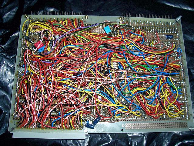
From your photos, it looks like D7..D0 are connected correctly.
Please check, if AS is tied to GND indeed, and if A2..0 are connected correctly.
Also, please check the 74HCT00 and 74HCT04 wiring, to be sure that there is nothing wrong with /IOCE, /WE, /RD.
For your next build, I would suggest not to have wires below the IC sockets (for simplifying debugging/modifying the hardware),
also it would be better to use the more expensive IC sockets with precision pins (because > 10 times of plugging/unplugging a chip won't do good to the sockets you are using).
Another trick for simplifying debugging is to stick
with the resistor color code for the wires of the bus lines,
like D0=black, D1=brown, D2=red, D3=yellow (if you can't buy orange), D4=black again etc.
Another trick is to have labels covering the top of the ICs, with printed info which signal is on which IC pin (so you won't have to look into the schematics too often).
I've checked A0..A2 are connected correctly and AS is wired to ground as well.
So I guess the problem really must be somewhere with the 74HCT logic or the wiring around there. I'll go thru the whole board checking for shorts between bus lines and correct wiring and post an update once I've done that.
Thanks for the hint with the wire colors using resistor color code. I haven't thought of that yet. That'll make it a a lot easier to debug than just one color for each bus.
This actually is one of the very few builds where I've crammed so many wires under the sockets since I thought looping this amount of wires around the sockets might take up too much space and the local parts shop here has got only one size of perfboard. (wasn't fun to do that anyways since I soldered the sockets in first)
Regarding the IC sockets I'm well aware that they are not very durable but they usually do the job well enough as it wasn't planned to run into a mysterious problem that forces me to swap the memory a few dozen times. I do by the way prefer this kind of socket over precision sockets since precision sockets make bending or breaking off IC legs too easy and its also difficult to stick salvaged parts with a little solder residue on the pins in those.


