mipspro wrote:
is there a way to set the jumpers to allow the use of a 2732 in U20?
Welcome.

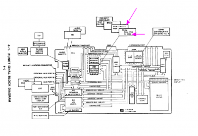
I had a quick look at the block diagram (below) contained in the
SYM-1 Reference Manual located in our
Synertek SYM-1 Resources page, and I gather that the jumpers would allow a 2332 or a 2532 to be fitted. But no word on 2732, although something may turn up if you dig a little deeper.
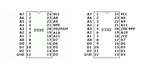
Otherwise, perhaps your best bet is to set the jumpers for 2532 then somehow make accommodation for the pinout differences with the 2732 you actually intend to use. Looks like you could attach the 2732's /CE and /OE together and drive them from pin 20 of the "2532" -- PD/PGM. That would be quite easy, mechanically, given how the pins line up.
If there's further troubleshooting to be done we're willing to help. It may be best to take your hunch about the 2332 being defective with a grain of salt.
Have fun, and keep us posted,
Jeff
edit: I didn't check the pinout for 2332. Possibly your task would be easier if the jumpers were set for it (rather than 2532).
Attachment:
 Sym-1 block diagram.png [ 88.62 KiB | Viewed 954 times ]
Attachment:
 2532-2732.png [ 4.85 KiB | Viewed 954 times ]
_________________
In 1988 my 65C02 got six new registers and 44 new full-speed instructions!
https://laughtonelectronics.com/Arcana/ ... mmary.html

