6502.org Forum  Projects  Code  Documents  Tools  Forum
It is currently Wed May 08, 2024 6:07 am

All times are UTC


Post new topic Reply to topic  [ 14 posts ] 
Author Message
PostPosted: Sun Apr 19, 2020 1:21 am 
Offline

Joined: Sat Apr 11, 2020 7:28 pm
Posts: 341
Hi all. I originally wrote this in another place, and it seems to me this is a good place to share it, of course to get comments and corrections from all of you. Thanks in advance.

6567 preliminary (it seems to be the only ones available everywhere) spec sheets says that an horizontal raster line takes always 520 clock cycles.

Attachment:
image.png
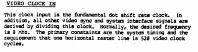
image.png [ 46.79 KiB | Viewed 1880 times ]


Those cycles are NOT CPU-clocked cycles for me, but VIC-clocked cycles. As you may know, the VIC draws 8 pixels by every CPU cycle. That's why the dot clock is eight times greater that the system clock. So if we divide 520 cycles by 8, we get 65 cycles, and that matches what the VIC timing specs says, that every horizontal raster line takes 63-65 cpu clock cycles.

Also, I've checked what's the duration of a line scan in both NTSC and PAL video signals standard. In NTSC, an horizontal line takes 63,5 microseconds to be drawn, and in PAL, 64 microseconds.

So, the VIC-II does access the memory 64 times minimum during every horizontal raster line, to read each one of the bytes that conforms a character or a bitmap. Additionally, access to sprite data and memory refreshing does requiere memory access (bad lines comes here) and there are also idle accesses that does 'nothing' but are part of the timing.

As you may know, the 65xx family of chips does use the high and low parts of a cycle to take turns accessing memory. So the memory actually gets accessed twice in every system clock cycle. It's like the memory running at 2mhz but actually stepping twice when the rest of the system steps once.

That said, the memory gets accessed 128 times a horizontal raster line. If an horizontal raster line takes ~64 microseconds, then every memory access takes 0,5 microseconds which is 500 nanoseconds.

The LH2464-12 memory chip that my '64 sports does an access time of 120 ns, so it does gracefully serves whatever thing both the CPU and the VIC does they ask it to do (read or write).

So... If a read of write of the VIC or the CPU every 500 ns... but the memory itself runs at 120ns, it could be said that there are 380ns of spare or idle time where the memory could be accessed to be read or written to, with neither the CPU or the VIC noticing it. And with 120ns of speed, it would mean that at least two or even very carefully timed three times it could be done.

What is the thing to be know? The actual amount of time 65xx chips leave the memory chips alone.

Code:
<------ high phase -----><------ low phase ------>    system clock cycle
0    1    2    3    4    5    6    7    8    9     \ 
02468024680246802468024680246802468024680246802468  > nanoseconds
00000000000000000000000000000000000000000000000000 |                 
-------------------------------------------------- / 
CCCCCCC                  CCCCCCC                      65xx chip memory access (VIC-II or CPU)
       FFFFFFFFFFFFFFFFFF       FFFFFFFFFFFFFFFFFF    Free? Idle? Spare? time of no memory access


That is the time chart I've thought. In theory, all those F are when the system RAM could be accessed with no CPU or VIC-II involved. But even better: with the CPU disabled, the times where the VIC permits the 6510 to access the memory, could be got by an external CPU to write to the memory before the VIC does access to it again to fetch data.

But the question after all of this is:
Is the memory actually free when one of the 65xx chip ends its turn of read/write to the memory chips?

Do any of this actually makes sense?


Top
 Profile  
Reply with quote  
PostPosted: Sun Apr 19, 2020 5:30 am 
Offline
User avatar

Joined: Thu Dec 11, 2008 1:28 pm
Posts: 10800
Location: England
Hi! I think you've mixed in a lot of C64 specific information there, which in principle could be separated from 6502 information. So, for example, one should say that the 6502 makes a single memory access in each clock cycle that it sees, and the surrounding system is free to interleave other memory accesses in between, and also free to adjust the clocks that the 6502 sees.

For example, Acorn's Electron makes two RAM accesses for each 6502 access, because the RAM is only 4 bits wide. It also interleaves CPU and video accesses, and it stops the CPU clock when the video needs more bandwidth.

The C64's system design with the VIC-II also does things... things which I am less aware of, because I'm not an expert on that system.

For sure, with sufficiently fast memory, one could design a system which makes 2, 3 or even 4 memory accesses within one 6502 clock. There's only a practical upper limit, as it's all about the length of time an access takes, including bus turnaround time, compared to the time between falling edges of the 6502 clock.

It is true that it's relatively straightforward to interleave CPU and non-CPU, and that's something that's been done in many 6502 systems, including Apple II.

The more complex the memory access pattern, the more chips it will take to do it.


Top
 Profile  
Reply with quote  
PostPosted: Sun Apr 19, 2020 6:59 am 
Offline

Joined: Mon May 21, 2018 8:09 pm
Posts: 1462
There is of course a complication, in that "120ns" memory cannot always be accessed every 120ns. The 120ns rating refers to the latency of a read access, measured between the /RAS strobe and data being guaranteed valid on the bus. But after that, there are two things which need to happen before the next /RAS strobe, beginning a new independent access, can occur. It would be reasonable to assume that 120ns memory can only sustain an access every 250ns or more, and that's if you get the timing precisely right - difficult to do with LS-TTL or NMOS logic which tends to have weak pull-up capabilities. The BBC Micro managed it, though it was using 100ns DRAM to get a guaranteed cycle time below 250ns.

We are of course talking about DRAM here. DRAM has very different access characteristics to SRAM. When building a new SBC, you would usually use SRAM because it's now cheap enough in hobbyist-computer quantities, and both fast and easy to interface to. But a home computer of circa 1980 would use DRAM, and the C64 is no exception.

I've attached representative portions of a contemporary datasheet which illustrates the problem. With 120ns memory, you could squeeze three 270ns accesses into a 1MHz overall clock cycle, but if you already have two equally-spaced accesses in that cycle, you won't be able to add another one between them.


Attachments:
Screenshot 2020-04-19 09.56.10.png
Screenshot 2020-04-19 09.56.10.png [ 460.37 KiB | Viewed 1865 times ]
Screenshot 2020-04-19 09.55.31.png
Screenshot 2020-04-19 09.55.31.png [ 155.83 KiB | Viewed 1865 times ]
Top
 Profile  
Reply with quote  
PostPosted: Sun Apr 19, 2020 1:21 pm 
Offline

Joined: Sat Apr 11, 2020 7:28 pm
Posts: 341
BigEd wrote:
Hi! I think you've mixed in a lot of C64 specific information there, which in principle could be separated from 6502 information.


Yes, you are right. This C64 post is maybe too specific. Also, it does reflects the specifics of the 65xx architecture. This could be applied to any of the systems you name.

Chromatix wrote:
There is of course a complication, in that "120ns" memory cannot always be accessed every 120ns.


Yes, they show in schematics the timing of what happens during the actual "read" operation, but they don't usually show what happens before and after that. And also, by looking many other things the memory does, it's clear that the actual speed can be even four time the announced one.

So a logic analyzer or an oscilloscope with enough resolution and long term logging capabilities is required to get the actual free time the memory is not accessed by any of the 65xx chips, to try to adjust a third player there.


Top
 Profile  
Reply with quote  
PostPosted: Sun Apr 19, 2020 1:47 pm 
Offline
User avatar

Joined: Thu Dec 11, 2008 1:28 pm
Posts: 10800
Location: England
BTW I don't have any big problem with C64 questions, it's just that it might be a bit of a minority interest. Also, although the VIC-II might have a 65xx part number, I think it's better always to mention that you mean a VIC-II system - saying 65xx would, to me, mean one of the 6502 type of CPUs. (I wouldn't expect 65xx to mean a 6522, for example, or any other peripheral.)

I think the general picture is that video, or any other DMA, will have to produce addresses which have to be routed to the RAM. So there's a need for some kind of multiplexing or three-state drive, which takes up some of the cycle time. There's a need to decide how to slice up the clock cycle, which may be to use the two phases, and the two phases may be the same length, or not. (The Oric, I think, divides up the clock cycle in a more interesting way.)

There are topics nearby about timing - it's useful to have in mind the meaning of setup, hold, clock-to-output, access time, and time to Z. Understand what causes what, rather than just recognising what is usually done. When you read a datasheet, see the difference between numbers which describe, and numbers which constrain.

Some useful threads:
Timing Diagrams. Visualizing 65xx Timing
Clock skew between glue logic and the CPU
RDY vs CLOCK STRETCHING. Includes 2 very simple circuits.


Top
 Profile  
Reply with quote  
PostPosted: Sun Apr 19, 2020 2:23 pm 
Offline
User avatar

Joined: Thu Dec 11, 2008 1:28 pm
Posts: 10800
Location: England
Just seen your post elsewhere. As the C64 timing has some interesting details and might not be native for many here, here's a couple of links:

VIC Timing Chart ("a comprehensive visualisation of the behaviour of the VIC chip")
the VIC article by Christian Bauer (1996)
the addendum by the VICE team (2010)

I'll also mention badlines, to help with future searches. And Commodore 64.


Top
 Profile  
Reply with quote  
PostPosted: Sun Apr 19, 2020 4:48 pm 
Offline

Joined: Sat Apr 11, 2020 7:28 pm
Posts: 341
Well... Yes, this has to do with VIC-II and 6510 as it's the origin of the hack someone else and me are thinking about.

But I think it could be exported to many other 65xx based designs.

Yes, this is more something about timing that specific to how the VIC-II and the CPU works, but of course the internals of both of them has to be known to make this to work.

If I by myself can clarify or give info about this, I will post here. But it would be nice to have someone with more equipment and knowledge than me to kick in and make that measurements to see if all of this do actually makes sense or is it an impossible.


Last edited by tokafondo on Sun Aug 09, 2020 2:44 pm, edited 1 time in total.

Top
 Profile  
Reply with quote  
PostPosted: Sun Apr 19, 2020 5:47 pm 
Offline
User avatar

Joined: Thu Dec 11, 2008 1:28 pm
Posts: 10800
Location: England
I think the timing question is fairly clear, in the abstract: if you have really fast memory, you can get more accesses into a given time. It's the practicalities of taking control of the bus, latching signals, decoding what needs to be done, which would need fleshing out.

In the case of both the VIC and the 6502 (6510) the existing accesses don't line up like on your diagram: the addresses will be produced relatively early in the phase, and the action on the databus takes place relatively late. If you're using the address bus for other purposes, you need to give back control to the old chips afterwards, but in enough time for them to meet timing.

It's a bit of a surprise to me that the C64 has such fast RAM chips. I can think of two possible reasons:
- that something in the system is slow enough that these fast chips were needed
- these fast chips were commodity parts and are much faster than they need to be

How do you plan to connect into the c64 system to take control of the busses?


Top
 Profile  
Reply with quote  
PostPosted: Sun Apr 19, 2020 8:07 pm 
Offline

Joined: Fri Apr 06, 2018 4:20 pm
Posts: 94
BigEd wrote:
It's a bit of a surprise to me that the C64 has such fast RAM chips. I can think of two possible reasons:
- that something in the system is slow enough that these fast chips were needed
- these fast chips were commodity parts and are much faster than they need to be

How do you plan to connect into the c64 system to take control of the busses?


The very first C64s came with 200ns RAM, usually ceramic and would be the bare minimum speed required to share the bus between the VIC-II and the 6510. Between 1982 and 1984 mostly.

Most C64s I’ve seen come with 150ns RAM, which seems to be the standard 1984 and after.

I’ve never seen 120ns RAM in a C64 but given how Commodore sourced whatever they could get a bargain on I don’t doubt it happened.


Top
 Profile  
Reply with quote  
PostPosted: Sun Apr 19, 2020 8:36 pm 
Offline
User avatar

Joined: Thu Dec 11, 2008 1:28 pm
Posts: 10800
Location: England
Thanks!


Top
 Profile  
Reply with quote  
PostPosted: Wed Aug 05, 2020 5:28 am 
Offline

Joined: Tue May 05, 2009 2:49 pm
Posts: 108
Not sure if it's already been noted, but the 6510 will consume cycles until the current instruction is finished. So, the VIC-II signals 3 cycles early when it needs the entire cycle width. This means that the cycles at the very end of a string of CPU cycles will not always be available. If the instruction in the fetch cycle when the CPU is signaled to give up teh bus is a NOP or 1 byte 2 cycle instruction, 2 cycles of useful CPU time will go unused, as far as I can see.

Jim


Top
 Profile  
Reply with quote  
PostPosted: Thu Aug 06, 2020 4:56 am 
Offline

Joined: Tue Jul 24, 2012 2:27 am
Posts: 672
Hmm, it's the IRQ/NMI behavior that finishes out the entire instruction, which could be up to 6 or so more cycles away, as interrupts need to occur on a whole instruction boundary.

Had to re-read up on it, but the RDY pin waits until the next read cycle to pause, allowing any write cycles to pass through first. It only needs 3 cycles to settle because that's the maximum number of consecutive writes that can occur (during BRK/interrupt stack pushing). The rest of the instruction will finish after the pin clears, so this is a mid-instruction state that it pauses in. It can't serialize that state externally, but does allow faster access to the bus than waiting for some full instructions to finish. I believe this means that RMW instructions could be non-atomic if something else grabs the bus and alters the location between the RM and the W.

If you wanted to be hackish, I think that during those 3 cycles you could test to see if a write is not performed, and grab the bus earlier. 3 cycles is just guaranteed safe.

_________________
WFDis Interactive 6502 Disassembler
AcheronVM: A Reconfigurable 16-bit Virtual CPU for the 6502 Microprocessor


Top
 Profile  
Reply with quote  
PostPosted: Fri Aug 07, 2020 4:12 am 
Offline
User avatar

Joined: Sun Dec 29, 2002 8:56 pm
Posts: 449
Location: Canada
Just to throw another monkey wrench into the parley, most drams are capable of fast-paged mode in which the column address is allowed changes while CAS is low. The access time for data read in fast page mode is usually the CAS access time, which is much less than the access time of the dram. The 1MHz clock is such a long period that it might be possible to triple up on the CAS access for ½ a clock cycle. But the access has to be within the same dram page. So, it wouldn’t help with the random cpu accesses, but the VIC chip accesses memory in a linear fashion. It may be possible to get higher display resolution or more sprites if fast page mode were used with the ram. -> it should be possible to upgrade the 64 a little bit.
Increasing the dram access frequency also would likely increase the power supply requirements and heat dissipation. Might need a better power supply with a fan.

_________________
http://www.finitron.ca


Top
 Profile  
Reply with quote  
PostPosted: Fri Aug 07, 2020 5:51 am 
Offline

Joined: Tue Jul 24, 2012 2:27 am
Posts: 672
Of course, that also assumes that the DRAMs can be on an isolated clock signal from the rest of the chips, too. Not sure how the specifics of that are wired in the C64 regarding the PLA and expansion port and whatnot.

_________________
WFDis Interactive 6502 Disassembler
AcheronVM: A Reconfigurable 16-bit Virtual CPU for the 6502 Microprocessor


Top
 Profile  
Reply with quote  
Display posts from previous:  Sort by  
Post new topic Reply to topic  [ 14 posts ] 

All times are UTC


Who is online

Users browsing this forum: No registered users and 4 guests


You cannot post new topics in this forum
You cannot reply to topics in this forum
You cannot edit your posts in this forum
You cannot delete your posts in this forum
You cannot post attachments in this forum

Search for:
Jump to: