6502.org Forum  Projects  Code  Documents  Tools  Forum
It is currently Wed Jul 03, 2024 8:39 am

All times are UTC


Post new topic Reply to topic  [ 8 posts ] 
Author Message
PostPosted: Tue Aug 07, 2018 1:14 pm 
Offline

Joined: Sat Aug 04, 2018 3:44 pm
Posts: 2
Hej everybody,

I am new to this forum, new to the 6502 processor, this is my first post in the forum, and it is directly my first question.

After reading some blogposts, such as,
I wanted to experiment a bit with the 65c02s. Basically, I just want to start my experiments as many others with a hard wired `NOP` operation as described in http://www.plingboot.com/2015/10/homebrew-6502-part-2/

However, I am wondering a bit about the values that I read from the address lines. I am especially wondering about three things:

  • When reset, should I not see $FFFC and $FFFD on the address lines?
    The Western Design Center Manual says:
    Quote:
    When a positive edge is detected, there will be a reset sequence lasting seven clock cycles. The program counter is loaded with the reset vector from locations FFFC (low byte) and FFFD (high byte).

    As you can see on my log below, I see something like $FC in both resets but not a consecutive $FFFC and $FFFD as expected. Additionally, I cannot see those seven clock cycles before "counting" on the address lines starts.
  • Why are some addresses left out?
    As you can see in the log below, there is for example a jump from `0xEB 0x0` to `0xEB 0x2`, one from `0xEB 0x2` to `0xEB 0x4`, etc.
    I would have expected something like `0xEB 0x0` to `0xEB 0x1` to `0xEB 0x2` to `0xEB 0x3` to `0xEB 0x4`, etc.
  • Why are some of the addresses there for more than a clock cycle?
    For example, in the log below, `0xEB 0xA` is read 9 times in a row, `0xEB 0x14` is read 8 times in a row, etc.
    I would have expected each number to appear once per clock cycle.


In the following is an excerpt from a log of the address lines with my comments after the `<--` arrow on the right hand side.

Code:
00000000 00000000 : 0x0 0x0    RWB: 1    SYNC: 1
11111111 11101010 : 0xFF 0xEA    RWB: 1    SYNC: 0      <-- First reset
11111111 11101010 : 0xFF 0xEA    RWB: 1    SYNC: 0
00000001 11111100 : 0x1 0xFC    RWB: 1    SYNC: 0
11101010 11110000 : 0xEA 0xF0    RWB: 1    SYNC: 0
11101010 11110101 : 0xEA 0xF5    RWB: 1    SYNC: 0
11101010 11111010 : 0xEA 0xFA    RWB: 1    SYNC: 0
11101010 11111111 : 0xEA 0xFF    RWB: 1    SYNC: 0
11101011 00000000 : 0xEB 0x0    RWB: 1    SYNC: 0
11101011 00000010 : 0xEB 0x2    RWB: 1    SYNC: 0
11101011 00000100 : 0xEB 0x4    RWB: 1    SYNC: 0
11101011 00000110 : 0xEB 0x6    RWB: 1    SYNC: 0
11101011 00001000 : 0xEB 0x8    RWB: 1    SYNC: 0
11101011 00001010 : 0xEB 0xA    RWB: 1    SYNC: 0
11101011 00001100 : 0xEB 0xC    RWB: 1    SYNC: 0
11101011 00001110 : 0xEB 0xE    RWB: 1    SYNC: 0
11101011 00010000 : 0xEB 0x10    RWB: 1    SYNC: 0
11101011 00010010 : 0xEB 0x12    RWB: 1    SYNC: 0
11101011 00010100 : 0xEB 0x14    RWB: 1    SYNC: 0
11101011 00010110 : 0xEB 0x16    RWB: 1    SYNC: 0
11101011 00011000 : 0xEB 0x18    RWB: 1    SYNC: 0
11101011 00011010 : 0xEB 0x1A    RWB: 1    SYNC: 0
11101011 00011100 : 0xEB 0x1C    RWB: 1    SYNC: 0
11101011 00011110 : 0xEB 0x1E    RWB: 1    SYNC: 0
11101011 00100000 : 0xEB 0x20    RWB: 1    SYNC: 0
11101011 00100001 : 0xEB 0x21    RWB: 1    SYNC: 0
11101011 00100010 : 0xEB 0x22    RWB: 1    SYNC: 1
11101011 00100100 : 0xEB 0x24    RWB: 1    SYNC: 0
11101011 00100110 : 0xEB 0x26    RWB: 1    SYNC: 0
11101011 00101000 : 0xEB 0x28    RWB: 1    SYNC: 0
11101011 00101001 : 0xEB 0x29    RWB: 1    SYNC: 0
11101011 00101010 : 0xEB 0x2A    RWB: 1    SYNC: 0
11101011 00101100 : 0xEB 0x2C    RWB: 1    SYNC: 0
11101011 00101110 : 0xEB 0x2E    RWB: 1    SYNC: 0
11101011 00110000 : 0xEB 0x30    RWB: 1    SYNC: 0
11101011 00110001 : 0xEB 0x31    RWB: 1    SYNC: 1
11101011 00110010 : 0xEB 0x32    RWB: 1    SYNC: 0
11101011 00110100 : 0xEB 0x34    RWB: 1    SYNC: 0
11101011 00110110 : 0xEB 0x36    RWB: 1    SYNC: 0
11101011 00111000 : 0xEB 0x38    RWB: 1    SYNC: 0
11101011 00111010 : 0xEB 0x3A    RWB: 1    SYNC: 0
11101011 00111100 : 0xEB 0x3C    RWB: 1    SYNC: 0
11101011 00111110 : 0xEB 0x3E    RWB: 1    SYNC: 0
11101011 01000000 : 0xEB 0x40    RWB: 1    SYNC: 0
11101011 01000001 : 0xEB 0x41    RWB: 1    SYNC: 0
11101011 01000010 : 0xEB 0x42    RWB: 1    SYNC: 0
11101011 01000011 : 0xEB 0x43    RWB: 1    SYNC: 0
11101011 01000100 : 0xEB 0x44    RWB: 1    SYNC: 0
11101011 01000101 : 0xEB 0x45    RWB: 1    SYNC: 0
11101011 01000110 : 0xEB 0x46    RWB: 1    SYNC: 0
11101011 01000111 : 0xEB 0x47    RWB: 1    SYNC: 0
11101011 01001000 : 0xEB 0x48    RWB: 1    SYNC: 0
11101011 01001001 : 0xEB 0x49    RWB: 1    SYNC: 0
11101011 01001010 : 0xEB 0x4A    RWB: 1    SYNC: 0
11101011 01001011 : 0xEB 0x4B    RWB: 1    SYNC: 0
11101011 01001100 : 0xEB 0x4C    RWB: 1    SYNC: 0
11101011 01001110 : 0xEB 0x4E    RWB: 1    SYNC: 0
11101011 01010011 : 0xEB 0x53    RWB: 1    SYNC: 0
11101011 01011000 : 0xEB 0x58    RWB: 1    SYNC: 0
11101011 01011101 : 0xEB 0x5D    RWB: 1    SYNC: 0
11101011 01100011 : 0xEB 0x63    RWB: 1    SYNC: 0
11101011 01101001 : 0xEB 0x69    RWB: 1    SYNC: 0
11101011 01101110 : 0xEB 0x6E    RWB: 1    SYNC: 0
11101011 01110011 : 0xEB 0x73    RWB: 1    SYNC: 0
11101011 01111000 : 0xEB 0x78    RWB: 1    SYNC: 0
11101011 01111101 : 0xEB 0x7D    RWB: 1    SYNC: 0
11101011 10000010 : 0xEB 0x82    RWB: 1    SYNC: 0
11101011 10000111 : 0xEB 0x87    RWB: 1    SYNC: 0
11101011 10001100 : 0xEB 0x8C    RWB: 1    SYNC: 0
11101011 10010001 : 0xEB 0x91    RWB: 1    SYNC: 0
11101011 10010110 : 0xEB 0x96    RWB: 1    SYNC: 0
11101011 10011011 : 0xEB 0x9B    RWB: 1    SYNC: 0
11101011 10011110 : 0xEB 0x9E    RWB: 1    SYNC: 0
11101011 10100100 : 0xEB 0xA4    RWB: 1    SYNC: 0
11101011 10101001 : 0xEB 0xA9    RWB: 1    SYNC: 0
11101011 10101110 : 0xEB 0xAE    RWB: 1    SYNC: 0
11101011 10110011 : 0xEB 0xB3    RWB: 1    SYNC: 0
11101011 10111000 : 0xEB 0xB8    RWB: 1    SYNC: 0
11101011 10111101 : 0xEB 0xBD    RWB: 1    SYNC: 0
11101011 11000010 : 0xEB 0xC2    RWB: 1    SYNC: 0
11101011 11000111 : 0xEB 0xC7    RWB: 1    SYNC: 0
11101011 11001011 : 0xEB 0xCB    RWB: 1    SYNC: 0
11101011 11010000 : 0xEB 0xD0    RWB: 1    SYNC: 0
11101011 11010101 : 0xEB 0xD5    RWB: 1    SYNC: 1
11101011 11011010 : 0xEB 0xDA    RWB: 1    SYNC: 1
11101011 11100001 : 0xEB 0xE1    RWB: 1    SYNC: 0
11101011 11100111 : 0xEB 0xE7    RWB: 1    SYNC: 0
11101011 11101100 : 0xEB 0xEC    RWB: 1    SYNC: 0
00000001 11111100 : 0x1 0xFC    RWB: 1    SYNC: 0       <-- second reset
11101010 11101111 : 0xEA 0xEF    RWB: 1    SYNC: 0
11101010 11110100 : 0xEA 0xF4    RWB: 1    SYNC: 0
11101010 11111001 : 0xEA 0xF9    RWB: 1    SYNC: 0
11101010 11111110 : 0xEA 0xFE    RWB: 1    SYNC: 0
11101011 00000011 : 0xEB 0x3    RWB: 1    SYNC: 0
11101011 00001000 : 0xEB 0x8    RWB: 1    SYNC: 0
11101011 00001101 : 0xEB 0xD    RWB: 1    SYNC: 0
11101011 00010011 : 0xEB 0x13    RWB: 1    SYNC: 0
11101011 00011000 : 0xEB 0x18    RWB: 1    SYNC: 0
11101011 00011101 : 0xEB 0x1D    RWB: 1    SYNC: 0
11101011 00100010 : 0xEB 0x22    RWB: 1    SYNC: 0
11101011 00100100 : 0xEB 0x24    RWB: 1    SYNC: 0
11101011 00100101 : 0xEB 0x25    RWB: 1    SYNC: 0
11101011 00100110 : 0xEB 0x26    RWB: 1    SYNC: 0
11101011 00101000 : 0xEB 0x28    RWB: 1    SYNC: 0
11101011 00101001 : 0xEB 0x29    RWB: 1    SYNC: 0
11101011 00101010 : 0xEB 0x2A    RWB: 1    SYNC: 0


My setup is the following:

  • I have an Arduino Mega2550, which I use to provide 5V, create a clock signal, read the address bus, and to read the `SYNC` and the `RWB` pin
  • I am using a WDC 65c02s (W65C02S6TPG-14)
  • Those pins pulled-high via 3.3kohm pull-up resitistors are the same as in the L-Star computer, see https://github.com/JacGoudsmit/L-Star

An illustration of my current setup can be seen in the following picture:
Image


My hypothesis is, that the clock signal is not sufficiently clean. A clock signal with a lot of ringing could cause the processor continuing NOPing without my program reading the address lines. Unfortunately, I do not have access to any kind of oscilloscope to verify this.

Do you have any idea why I am seeing those weird behaviour when reading the address line? Is there anything I can do to my circuit to make it work as expected? If it is something like adding another decoupling capacitor somewhere, where and how should that be done?


In the following and for completness the Arduino program, which I am using for the experiment.

Code:
#define CLOCK 52
#define SYNC 50
#define RWB 51
#define A0 22
#define A1 23
#define A2 24
#define A3 25
#define A4 26
#define A5 27
#define A6 28
#define A7 29
#define A8 30
#define A9 31
#define A10 32
#define A11 33
#define A12 34
#define A13 35
#define A14 36
#define A15 37


void setup() {
    pinMode(CLOCK, OUTPUT);
    digitalWrite(CLOCK, LOW);
    Serial.begin(115200);
    delay(500);
}

void loop() {
    digitalWrite(CLOCK, LOW);
    delay(100);
    digitalWrite(CLOCK, HIGH);

    byte a0 = digitalRead(A0);
    byte a1 = digitalRead(A1);
    byte a2 = digitalRead(A2);
    byte a3 = digitalRead(A3);
    byte a4 = digitalRead(A4);
    byte a5 = digitalRead(A5);
    byte a6 = digitalRead(A6);
    byte a7 = digitalRead(A7);
    byte a8 = digitalRead(A8);
    byte a9 = digitalRead(A9);
    byte a10 = digitalRead(A10);
    byte a11 = digitalRead(A11);
    byte a12 = digitalRead(A12);
    byte a13 = digitalRead(A13);
    byte a14 = digitalRead(A14);
    byte a15 = digitalRead(A15);

    byte address_value_low  = a7 << 7;
    address_value_low  += a6 << 6;
    address_value_low  += a5 << 5;
    address_value_low  += a4 << 4;
    address_value_low  += a3 << 3;
    address_value_low  += a2 << 2;
    address_value_low  += a1 << 1;
    address_value_low  += a0;

    byte address_value_high  = a15 << 7;
    address_value_high  += a14 << 6;
    address_value_high  += a13 << 5;
    address_value_high  += a12 << 4;
    address_value_high  += a11 << 3;
    address_value_high  += a10 << 2;
    address_value_high  += a9 << 1;
    address_value_high  += a8;
   
    Serial.print(a15);
    Serial.print(a14);
    Serial.print(a13);
    Serial.print(a12);
    Serial.print(a11);
    Serial.print(a10);
    Serial.print(a9);
    Serial.print(a8);
    Serial.print(' ');
    Serial.print(a7);
    Serial.print(a6);
    Serial.print(a5);
    Serial.print(a4);
    Serial.print(a3);
    Serial.print(a2);
    Serial.print(a1);
    Serial.print(a0);
    Serial.print(" : 0x");
    Serial.print(address_value_high, HEX);
    Serial.print(" 0x");
    Serial.print(address_value_low, HEX);
    Serial.print("    RWB: ");
    Serial.print(digitalRead(RWB));
    Serial.print("    SYNC: ");
    Serial.print(digitalRead(SYNC));
    Serial.println();
}


Attachments:
File comment: Added breadboard schematics as attachement as suggested in replies.
nop_small.png
nop_small.png [ 272.85 KiB | Viewed 2558 times ]


Last edited by HelgeCPH on Wed Aug 08, 2018 10:19 am, edited 1 time in total.
Top
 Profile  
Reply with quote  
PostPosted: Tue Aug 07, 2018 1:54 pm 
Offline
User avatar

Joined: Thu Dec 11, 2008 1:28 pm
Posts: 10838
Location: England
Welcome!

Although it's possible to have clock problems, it might not be the first hypothesis. I see you have one bypass capacitor on the breadboard power rails - it would not be a bad idea to put another one nearer the actual power pins of the MPU.

But one thing sticks out: you are almost always, but not quite always, seeing SYNC as 0. To me, that means you might be sampling at a bad time relative to the clock edges. With EA as a NOP, you expect to see SYNC every other cycle, and for the address bus to increment every other cycle too.

If you are mis-sampling, then we shouldn't worry too much about the rest of the trace, until that problem is cleared.

It is odd to see several consecutive cycles with no change on the address pins. If you were sampling sometimes much too fast and sometimes much too slow, you'd see that.

I haven't skimmed your Arduino code. I probably should have.


Top
 Profile  
Reply with quote  
PostPosted: Tue Aug 07, 2018 2:12 pm 
Offline
User avatar

Joined: Fri Dec 11, 2009 3:50 pm
Posts: 3366
Location: Ontario, Canada
Welcome, HelgeCPH. For some reason I'm not able to view the image. May I suggest you attach it with your post? This forum (unlike many others) does allow that. :)

I agree with Ed. You need to find out why SYNC appears to be remaining low. Are you *sure* the RDY pin is being pulled up? You can verify that with just a voltmeter.

Yes, there could be a clocking issue, but there's a list of other factors I'd consider first. You might find there's a wiring error, and that the results reported by the Arduino are accordingly incorrect. BTW, remember it's possible to stop a WDC CPU at any time. So, for example, you can run the reset sequence in minute detail, stopping on every cycle and verifying the state of every pin with the voltmeter.


cheers,
Jeff

_________________
In 1988 my 65C02 got six new registers and 44 new full-speed instructions!
https://laughtonelectronics.com/Arcana/ ... mmary.html


Top
 Profile  
Reply with quote  
PostPosted: Tue Aug 07, 2018 2:36 pm 
Offline
User avatar

Joined: Thu Dec 11, 2008 1:28 pm
Posts: 10838
Location: England
OK, I had a skim of the sketch. Can I suggest a delay() after you raise the clock? 100 milliseconds is more than enough - even 1 millisecond should be enough. But possibly without a delay your clock pulse will be very short, depending on how fast the Arduino is.


Top
 Profile  
Reply with quote  
PostPosted: Tue Aug 07, 2018 3:12 pm 
Offline

Joined: Sun Jun 29, 2014 5:42 am
Posts: 337
My money is on insufficient decoupling capacitors. They need to be physically as close to the power pins of the 65C02 as possible. As well as a 0.1uF ceramic, I would add a 10uF electrolytic.

I would also route the ground connection from the Arduino board directly to the row in the breadboard where pin 21 is connected.

Dave


Top
 Profile  
Reply with quote  
PostPosted: Wed Aug 08, 2018 10:38 am 
Offline

Joined: Sat Aug 04, 2018 3:44 pm
Posts: 2
Thank you for the warm welcome and all your answers with hints!

@Dr Jefyll
Quote:
Welcome, HelgeCPH. For some reason I'm not able to view the image. May I suggest you attach it with your post? This forum (unlike many others) does allow that. :)

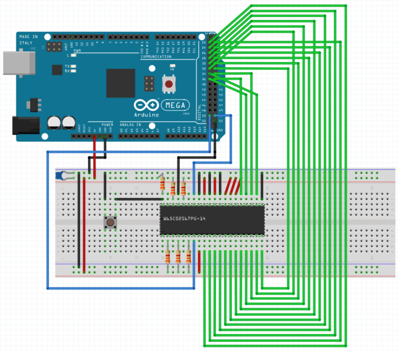
Right, I do not know why this happens, but I edited the post and added the illustration as attachement.

Quote:
I agree with Ed. You need to find out why SYNC appears to be remaining low. Are you *sure* the RDY pin is being pulled up? You can verify that with just a voltmeter.

Unfortunately, I do not have a proper voltmeter either. But I did what you suggested with the help of an LED, just to see if pins are high/low as expected.

When doing that, I figured out that my problem was really easy to solve, stupid, and I should have seen it before posting...

In the schematics I connected the clock signal to pin `53` of the Arduino. However, in my sketch I set the clock pin to `52`. That of course meant that there was no real clock signal coming to the MPU. In connection with the `loop` of the sketch I was mislead to that a clock signal was properly generated.


As I understand, the clock pin was floating and therefore something seemed to be happening anyways only with in weird steps. Is that understanding right?


@hoglet
Quote:
My money is on insufficient decoupling capacitors. They need to be physically as close to the power pins of the 65C02 as possible. As well as a 0.1uF ceramic, I would add a 10uF electrolytic.

Since I do not really know electronics, I have to ask here. Do I understand it correctly, that you suggest to add one leg of a decoupling capacitor to VDD (pin 8 of the MPU) and the other one of to ground? This is how I understand decoupling capacitors should be used but I am not sure if it is right.


Just for completeness an excerpt of the log in which now the SYNC signal is alternating, the address lines "count" properly, and in which the reset is properly visible via the addresses $FFFC and $FFFC
Code:
11101011 01111111 : 0xEB 0x7F    RWB: 1    SYNC: 1
11101011 10000000 : 0xEB 0x80    RWB: 1    SYNC: 0
11101011 10000000 : 0xEB 0x80    RWB: 1    SYNC: 1
11101011 10000001 : 0xEB 0x81    RWB: 1    SYNC: 0
11101011 10000001 : 0xEB 0x81    RWB: 1    SYNC: 1
11101011 10000010 : 0xEB 0x82    RWB: 1    SYNC: 0
11101011 10000010 : 0xEB 0x82    RWB: 1    SYNC: 1
11101011 10000011 : 0xEB 0x83    RWB: 1    SYNC: 0
11101011 10000011 : 0xEB 0x83    RWB: 1    SYNC: 1
11101011 10000100 : 0xEB 0x84    RWB: 1    SYNC: 0
11101011 10000100 : 0xEB 0x84    RWB: 1    SYNC: 1
11101011 10000101 : 0xEB 0x85    RWB: 1    SYNC: 0
11101011 10000101 : 0xEB 0x85    RWB: 1    SYNC: 1
11101011 10000110 : 0xEB 0x86    RWB: 1    SYNC: 0
11101011 10000110 : 0xEB 0x86    RWB: 1    SYNC: 1
11101011 10000111 : 0xEB 0x87    RWB: 1    SYNC: 0
11101011 10000111 : 0xEB 0x87    RWB: 1    SYNC: 1
11101011 10001000 : 0xEB 0x88    RWB: 1    SYNC: 0
11101011 10001000 : 0xEB 0x88    RWB: 1    SYNC: 1
11101011 10001001 : 0xEB 0x89    RWB: 1    SYNC: 0
11101011 10001001 : 0xEB 0x89    RWB: 1    SYNC: 1
11101011 10001010 : 0xEB 0x8A    RWB: 1    SYNC: 0
11101011 10001010 : 0xEB 0x8A    RWB: 1    SYNC: 1
11101011 10001011 : 0xEB 0x8B    RWB: 1    SYNC: 0
11111111 11111111 : 0xFF 0xFF    RWB: 1    SYNC: 1
11101011 10001100 : 0xEB 0x8C    RWB: 1    SYNC: 0
00000001 01110000 : 0x1 0x70    RWB: 1    SYNC: 0
00000001 01101111 : 0x1 0x6F    RWB: 1    SYNC: 0
00000001 01101110 : 0x1 0x6E    RWB: 1    SYNC: 0
11111111 11111100 : 0xFF 0xFC    RWB: 1    SYNC: 0
11111111 11111101 : 0xFF 0xFD    RWB: 1    SYNC: 0
11101010 11101010 : 0xEA 0xEA    RWB: 1    SYNC: 1
11101010 11101011 : 0xEA 0xEB    RWB: 1    SYNC: 0
11101010 11101011 : 0xEA 0xEB    RWB: 1    SYNC: 1
11101010 11101100 : 0xEA 0xEC    RWB: 1    SYNC: 0
11101010 11101100 : 0xEA 0xEC    RWB: 1    SYNC: 1
11101010 11101101 : 0xEA 0xED    RWB: 1    SYNC: 0
11101010 11101101 : 0xEA 0xED    RWB: 1    SYNC: 1
11101010 11101110 : 0xEA 0xEE    RWB: 1    SYNC: 0
11101010 11101110 : 0xEA 0xEE    RWB: 1    SYNC: 1
11101010 11101111 : 0xEA 0xEF    RWB: 1    SYNC: 0
11101010 11101111 : 0xEA 0xEF    RWB: 1    SYNC: 1


Top
 Profile  
Reply with quote  
PostPosted: Wed Aug 08, 2018 11:20 am 
Offline
User avatar

Joined: Thu Dec 11, 2008 1:28 pm
Posts: 10838
Location: England
Much better!


Top
 Profile  
Reply with quote  
PostPosted: Mon Aug 13, 2018 4:04 pm 
Offline
User avatar

Joined: Thu May 14, 2015 9:20 pm
Posts: 155
Location: UK
Hello HelgeCPH :D
HelgeCPH wrote:
@hoglet
Quote:
My money is on insufficient decoupling capacitors. They need to be physically as close to the power pins of the 65C02 as possible. As well as a 0.1uF ceramic, I would add a 10uF electrolytic.

Since I do not really know electronics, I have to ask here. Do I understand it correctly, that you suggest to add one leg of a decoupling capacitor to VDD (pin 8 of the MPU) and the other one of to ground? This is how I understand decoupling capacitors should be used but I am not sure if it is right.

With fast CMOS chips like the WDC65C02S, it's good practice to provide a short term supply of energy so that when the chip internal logic changes state, or when it changes the outputs from low to high or high to low, the current required can partially be supplied by the local energy store. This reduces the voltage drop that otherwise would occur due to the slight resistance of the wiring and inconnections between the power source and the chip. In electronics, the method of providing a local energy store is by connecting suitable capacitors as close as possible to the relevant chip(s). Ceramic 100nF (0.1uF) types (mostly multilayer known as MLCC) are used. In addition 10uF or 47uF 'low ESR' electrolytic capacitors are often used on the supply network. These are in simple terms, slower than the ceramic type, but can hold more energy. Hence are sometimes referred to as bulk decoupling.

For a simple breadboard circuit like yours, you could route the +5V and the 0V/GND wires directly from the Arduino to the breadboard connections strips that the 6502 power pins are in. Then put one capacitor lead in one of these strips, and use a wire to get the other capacitor lead to the other power pin strip. The idea being that the physical distance between each capacitor leg to the relevant power/ground pin of the chip be as short as possible.

And yes, without a reliable clock, microprocessors either don't do anything, or do strange things...

Have fun :D

Mark


Top
 Profile  
Reply with quote  
Display posts from previous:  Sort by  
Post new topic Reply to topic  [ 8 posts ] 

All times are UTC


Who is online

Users browsing this forum: No registered users and 10 guests


You cannot post new topics in this forum
You cannot reply to topics in this forum
You cannot edit your posts in this forum
You cannot delete your posts in this forum
You cannot post attachments in this forum

Search for:
Jump to: