I've been struggling off and on for the last few days.
I'm not near my board at the moment so I can't post a pic or schematics...but I can if they are needed.
Anyway, I'm having three different issues. The example I'm following is here:
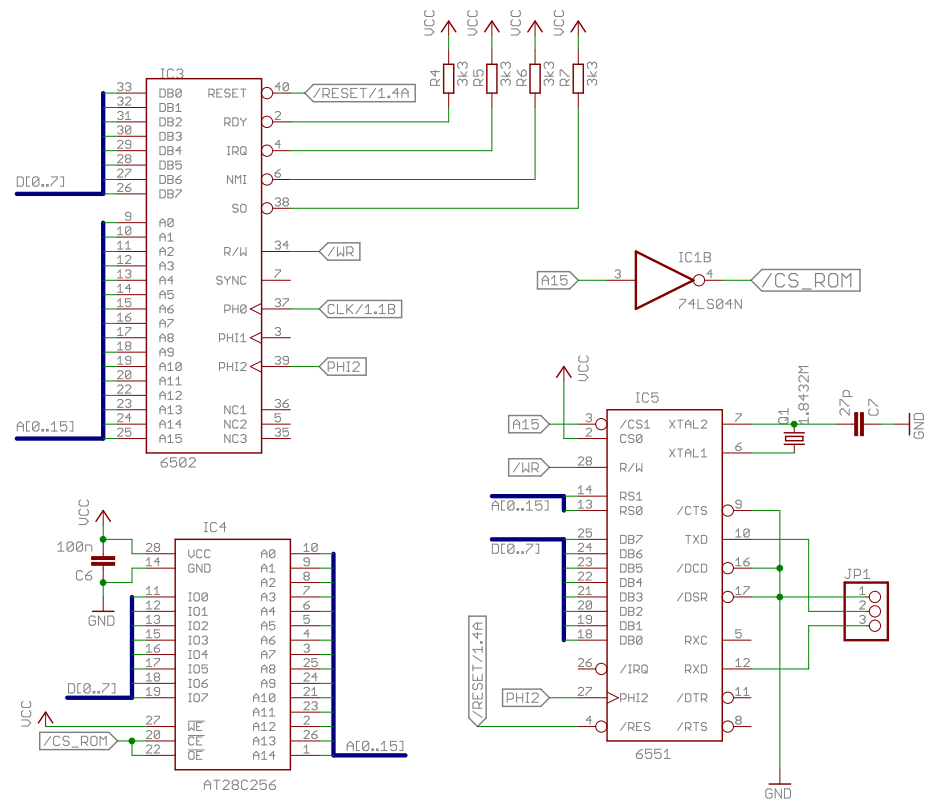
http://www.grappendorf.net/projects/6502-home-computer/acia-serial-interface-hello-world.htmlI've built that circuit for the most part. The differences are:
1) I'm using a 65C02 instead of the NMOS version.
2) I only have 8K EEPROMS and not 32K
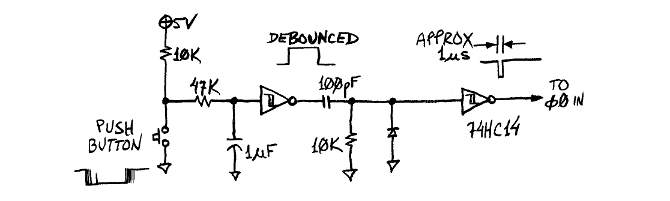
3) I have a 3k3 pull-up for RESET with a push-button to GND.
4) I have a 3.579545 MHz clock running through a 74'4040 counter to get a 1.79...MHz clock.
Here are the issues I'm having:
1) Power. The entire breadboard is only using 11 mA. I have the 65C02, a ripple counter, a hex inverter, ROM and ACIA and I'm only pulling 11mA? Sometimes it drops to 9mA. Something is wrong. I am using a bench power supply at 5v and 1A max. Each IC has a .1uF cap on VCC that is as close as I can get it. Since this is a large breadboard, I have large 1000uF electrolytic caps all over the board in hopes of providing enough power. But nothing seems to be using it. I have an LED on the opposite end of the board that lights up just fine and he's pulling an additional 12 mA. When the LED is plugged in, I pull 23 mA. No LED = 11 mA. Oh, each IC will read 4.9V on the high end and 4.2V on the low end.
2) ACIA clock. I have the 1.8xxx MHz crystal tied to pins 6/7 of the 65C51. I put a 22pF cap from pin 7 to GND. Sometimes it works, most of the time it doesn't. I then put another 22pF cap on pin 6 to GND and then it will work for a little while. Scope shows what I expect 1.8xxx MHz. If I wiggle the crystal around for a while, it will sometimes start clocking correctly. But 80% of the time, the scope just shows 5V straight line (well, a little ripple but mostly straight...especially with averaging turned on).
3) Serial data. The little program on the webpage I listed just performs a simple "hello world" over the serial port. Sometimes, and I mean just sometimes, I will get random garbage come over the terminal. But it's never "hello world". For serial communication, I am using this device:
https://www.parallax.com/product/32201. I am connecting the 65C51's TX pin to the RX of the PropPlug and the RX to the TX of the PropPlug. GND to GND. The PropPlug also has a "RESET" pin for rebooting the mCU but I'm not using that.
Here is what I've done to try and solve my issues (not a complete list!):
1) Large capacitors all over the board to help distribute power. I've seen the board pull as high as 63 mA but it usually drops to 11 quickly. I've put large caps near each IC in hopes that each would have their own power reserve (in addition to the decoupling caps mentioned above).
2) Plugged my frequency generator into pin 7 of the 65C51 with the exact frequency dialed in.
3) Made sure each wire was the same length for any bus. As best as I could. Checked, re-checked and re-checked 5 more times on my wiring. Since I am only using 8K ROM, I left A14 and A13 floating. (I've also grounded them at one point).
4) Lowered the system clock down to 3.579545 / 4 = < 1 MHz clock.
The schematics are almost exactly the same as the URL above. I can post some pictures later this evening. But I thought I would ask for guidance while it was still fresh in my mind.
Thanks for any help!
** EDIT **
BTW, I ordered a couple 32K EEPROM's (28C256) and 3 DS1813's.
Also, I just realized the "SBC-2 v2.5"
http://sbc.rictor.org/info2.html is pretty much exactly the computer I want to build. Stupid me! The only difference is that I want to integrate some AY audio chips and a TMS9918 eventually. I will look over that design too. Regardless, I'd like to know what I did wrong in my existing setup too.


