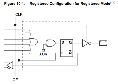
It looks like you worked around it by using separate "reset" logic within your PLD file, which seems fine as an option given such a reset signal exists and is guaranteed to last at least one clock tick. But regarding making a pin actually default to a different state, I don't believe this is possible with the ATF16V8. The flipflops in the macrocells always default to the "off" state, and their sense is inverted by an output driver on the way to the pin in a way that's not programmable, meaning the pins always default to high output level.
Attachment:
 16v8_reg_output_cell.png [ 42.27 KiB | Viewed 2958 times ]
It is possible to influence the logical default state for the pin as far as the rest of the PLD file is concerned though - which is useful if you're using the macrocell only for feedback logic and the electrical state of the physical pin doesn't matter to you (e.g. not connected). For one of my designs recently I had a two-bit "lock" state that's internal to the PLD, and I wanted it to default to "00". To do this I added inversion to the pin definition as below:
Code:
/* outputs */
pin 19 = !SHAD; /* Shadow-active state */
pin [ 17, 18 ] = [ !LOCK0, !LOCK1 ]; /* Lock state */
As the flipflop defaults to being "off", and thus the pin defaults to being "on", and my lock state is the opposite of the pin, my lock state bits both default to "off" as desired. Cupl enables the XOR gate and adjusts any expressions using my lock bits to have the opposite sense.
SHAD here is similar but this one is an actual electrical output, and I want SHAD to be off by default, so the electrical output has to be "!SHAD". The electrical output will again default high, so then SHAD is "off" as desired, and the rest of the circuit needs to cope with this signal being inverted.

