6502.org Forum  Projects  Code  Documents  Tools  Forum
It is currently Sat Apr 27, 2024 3:40 pm

All times are UTC


Post new topic Reply to topic  [ 17 posts ]  Go to page 1, 2  Next
Author Message
PostPosted: Wed Mar 29, 2023 8:04 am 
Offline
User avatar

Joined: Tue Feb 28, 2023 11:39 pm
Posts: 133
Location: Texas
I'm considering using some custom logic for the 6502/65816 builds I'm working on. And while I've found some information from searching the internet, seems like information on these devices is a bit of hit or miss; and I feel I'm still just about puzzled by what's out there when I first began my searching.

I did manage to pick up some ATF16V8 PLDs, and figured out how to program those and get them working; but I've quickly run into limits with what those can do, and I think in order to do some of the more complex things I'd like to do, I will need to move on to some CPLDs and/or FPGAs. As such I have some questions surrounding these things that I'm having trouble figuring out from internet searches.

FPGAs:
I did pick up a development board with an FPGA, and have tinkered with it a bit, but I'm not yet clear how I'd go about integrating it with my projects.

It looks like a good chunk of these are using 3.3V logic which would require some logic level shifting which I'd like to avoid if for no other reason then it's just adding more chips to the mix that add delays, and soldering work (they have a lot of pins!) and what not? (Maybe I'm over thinking it?) Are there any 5V CMOS options out there?

I've also noticed that, the board I have has a lot of support chips around the FPGA itself. I'm presuming some of these are just fancy things showing off what you can do with the FPGA, but I was wondering about how you go about programming just the raw FPGA itself. From my searching I want to say that seems what this JTAG thing is for, but all the information I can find is pretty sparse on details. With the PLD I have I can just drop them in my EEPROM programmer and call it done, but I don't think I'm going to find such a device that fits most of the surface mount packages I'm seeing the FPGAs in.

Finally, I'm a bit on the fence about these as they seem really powerful, esp. compared to the 65xxx chips, which begs the question of why would I not just use them to just include the CPU in them to begin with? (Just seems weird to slave the more powerful device off of the less capable chip like that, just curious what people think about this.)

CPLDs:
The CPLDs seemed interesting because it seems like they wouldn't just immediately overshadow the 65xxx processors, and are limited to more discrete logic operations. It also appears that there are some more 5V options.

However, they have the some of the same programming questions as the FPGA. Most appear to be PLCC or surface mount; what do you guys use to program these things?

The idea of having logic implemented in a re-programmable hardware language seems really appealing to me so I'd really like to learn more about these guys.


Top
 Profile  
Reply with quote  
PostPosted: Wed Mar 29, 2023 9:04 am 
Offline
User avatar

Joined: Thu Dec 11, 2008 1:28 pm
Posts: 10793
Location: England
I think the programmable logic route can be a very fine adventure!

You're right, the relative lack of 5V parts, or even 3V parts with 5 tolerance, is a bit of an obstacle, but it's not a barrier. It's fairly likely you'll need level shifters, either in your own design or built into a submodule that you make use of. These days a PCB house will often have an affordable option to include components, so if you pick parts from their list they will do some of the assembly for you. Another option is to use a dev board which already has what you want. (If it happens to have more, that's no problem.)

And yes, if you pick a capacious FPGA, it might well be large enough to contain a CPU, and that can be an interesting option. But you don't have to do it if you don't want to. One attraction of 8 bit computing is to have access to the address and data busses, and one attraction is to have a 40 pin DIP that you can point at as the CPU. Tastes vary, and there are many ways forward.

Both CPLDs and FPGAs will most probably be programmed over JTAG, which means there'll be a header, maybe 6 pins or 10 pins, maybe with a standard pinout, and you'll need something to program the device. That something could be a proprietary dongle, or it could be a Raspberry Pi (or Pico) or it could be something in between.

Have a good adventure, and keep in touch. Do some reading, ask some questions, do some experiments.

There are many previous posts and threads too, so have a look around.


Top
 Profile  
Reply with quote  
PostPosted: Wed Mar 29, 2023 9:21 am 
Offline
User avatar

Joined: Wed Feb 14, 2018 2:33 pm
Posts: 1398
Location: Scotland
I've used some GALs (22v10s) in my 6502/816 boards. Plenty old Lattice ones on ebay and compatible ATF ones (that need a different programmer) still in production.

For designing the logic I used GALASM which runs under Linux for me.

-Gordon

_________________
--
Gordon Henderson.
See my Ruby 6502 and 65816 SBC projects here: https://projects.drogon.net/ruby/


Top
 Profile  
Reply with quote  
PostPosted: Wed Mar 29, 2023 5:31 pm 
Offline
User avatar

Joined: Tue Feb 28, 2023 11:39 pm
Posts: 133
Location: Texas
BigEd wrote:
I think the programmable logic route can be a very fine adventure!

You're right, the relative lack of 5V parts, or even 3V parts with 5 tolerance, is a bit of an obstacle, but it's not a barrier. It's fairly likely you'll need level shifters, either in your own design or built into a submodule that you make use of. These days a PCB house will often have an affordable option to include components, so if you pick parts from their list they will do some of the assembly for you. Another option is to use a dev board which already has what you want. (If it happens to have more, that's no problem.)


That's good to know, I might have them handle the surface mount stuff which I'm just clumsy with.

Quote:
And yes, if you pick a capacious FPGA, it might well be large enough to contain a CPU, and that can be an interesting option. But you don't have to do it if you don't want to. One attraction of 8 bit computing is to have access to the address and data busses, and one attraction is to have a 40 pin DIP that you can point at as the CPU. Tastes vary, and there are many ways forward.


Not going to lie, there is something very satisfying about snapping an IC into a bread board or socket, almost like building a Lego set. :D

Quote:
Both CPLDs and FPGAs will most probably be programmed over JTAG, which means there'll be a header, maybe 6 pins or 10 pins, maybe with a standard pinout, and you'll need something to program the device. That something could be a proprietary dongle, or it could be a Raspberry Pi (or Pico) or it could be something in between.


Okay, I was thinking at least for the PLCC chips I could probably get a socket and make a small board with whatever I need to do it. Are the pins in usually suspect locations like VCC and Ground often are for 74 chips?

Quote:
Have a good adventure, and keep in touch. Do some reading, ask some questions, do some experiments.

There are many previous posts and threads too, so have a look around.


Yep, I've been poking around I has the brain juices flowing. :mrgreen:


Top
 Profile  
Reply with quote  
PostPosted: Wed Mar 29, 2023 5:39 pm 
Offline
User avatar

Joined: Tue Feb 28, 2023 11:39 pm
Posts: 133
Location: Texas
drogon wrote:
I've used some GALs (22v10s) in my 6502/816 boards. Plenty old Lattice ones on ebay and compatible ATF ones (that need a different programmer) still in production.


A couple more outputs than the 16V8s, but I need at least 11 lines for my address decoding I'm doing. >_<
Which is the first thing I was planning to try and use them for, I currently have 3~4 ICs handling that logic and I'd like to reduce that down to one IC and get the propagation delay down so I can look at boosting the clock speed on my 6502.

I've been eyeballing these ATF1502AS-7JX44 jobs, which seems like they'd have more than enough to do what I'd like initially. Seems like I could get my address decoding in there, plus (I hope) something to shadow the ROM into a faster RAM chip and then have it switch the clock on boot.

Quote:
For designing the logic I used GALASM which runs under Linux for me.

-Gordon


I'll check that out WinCupl is clearly a bit dated and has some.... ah.... "personality" let's say.


Top
 Profile  
Reply with quote  
PostPosted: Wed Mar 29, 2023 5:47 pm 
Offline
User avatar

Joined: Thu Dec 11, 2008 1:28 pm
Posts: 10793
Location: England
Oh, you'd normally program with JTAG in-circuit, no need to socket your chips, unless you expect to be swapping them for other reasons.


Top
 Profile  
Reply with quote  
PostPosted: Wed Mar 29, 2023 6:20 pm 
Offline
User avatar

Joined: Fri Aug 03, 2018 8:52 am
Posts: 745
Location: Germany
hmmm, i would personally always put PLCC and DIP chips in sockets, regardless of if you actually plan on taking them out again or not.
simply having the option to take them out without doing any desoldering is always nice to have.

but as Ed said, JTAG is designed for in-system programming, so you program the CPLD/FPGA while it's in your system using an onboard JTAG header.
said header has a standardized pinout, for the AT150x series of CPLDs it's this:
Attachment:
chrome_6lFAUuT1ot.png
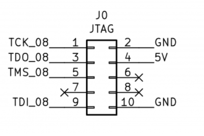
chrome_6lFAUuT1ot.png [ 266.26 KiB | Viewed 8772 times ]

also make sure to never use the JATG Pins for your logic, as that will disable JTAG. which casues some headaches!

also in regards to the voltage, 5V FPGAs pretty much don't exist (technically they do, but are too expensive to be worth it). but if you really want to use an FPGA, then you could design your whole system to run on 3.3V instead.
it shouldn't be that difficult, unless you plan on using some part that requires 5V signals, but even then you could connect that one using level shifters and have everything else still run at 3.3V.
though of course this is only really an option if you're planning a new system, and not when you already have one where you want to replace the existing logic with an FPGA.

Yuri wrote:
plus (I hope) something to shadow the ROM into a faster RAM chip and then have it switch the clock on boot.

hm, if you're using a 65c02 have you thought about making a simple RDY circuit to slow the CPU down when accessing the ROM?
obviously you lose some performance, but it seems much easier to implement. plus later on you can then go back and redo that logic to allow the CPU to disable the ROM (which then also disabled the RDY circuit).

Yuri wrote:
I'll check that out WinCupl is clearly a bit dated and has some.... ah.... "personality" let's say.

i found that using the commandline CUPL program directly works better.
alternatively you can use Verilog/VHDL with Quartus II web edition v13.0.
make your project around the MAX7000 series:
MAX7032 = ATF1502
MAX7064 = ATF1504
MAX7128 = ATF1508
then after synthesizing, use POF2JED to... well convert the .pof file from Quartus to a .jed file to program into the CPLD

it's a bit of a process, but i've been using it for years now and it works well enough.
but this sadly won't be an option if you're on Linux.


Top
 Profile  
Reply with quote  
PostPosted: Wed Mar 29, 2023 6:52 pm 
Offline

Joined: Fri Dec 21, 2018 1:05 am
Posts: 1076
Location: Albuquerque NM USA
Programmer for ATF150x is pretty expensive, over $60 last time I checked. EPM7xxx is equivalent to ATF150x but EPM7xxx programmer is cheap, under $10, shipping included. Designing EPM7xxx can be done with free-download Quartus tool, version 13 or earlier. The tool chain is straightforward. The big IF is where to find reliable EPM7xxx? You can try eBay only because of its excellent return policy because you'll like return many of them. If you do find a reliable source, buy bunch of them. You'll like CPLD so much, you'll regret only have purchased 10-20 of them from known good source.

You can pack lots of functions into even a 64-macrocell CPLD (ATF1504 or EPM7064S) such as a 64-byte boot ROM, serial port, I2C, compact flash interface, and address decode.
Bill


Top
 Profile  
Reply with quote  
PostPosted: Wed Mar 29, 2023 8:27 pm 
Offline
User avatar

Joined: Thu May 28, 2009 9:46 pm
Posts: 8144
Location: Midwestern USA
The Microchip ATF15xx series is 5-volt compatible and quite capable, being able to, among other things, support state machines. As Plasmo noted, you can do quite a bit with an ATF1504AS, which has 64 macrocells, 32 uncommitted I/O pins in a PLCC44 package, and is available in speed grades down to 7 nanoseconds. The largest member of the family is the ATF1508AS, with 128 MCs and 64 uncommitted I/O pins in a PLCC84 package.

These devices are also available in QFP100, giving even more I/O pins.

_________________
x86?  We ain't got no x86.  We don't NEED no stinking x86!


Top
 Profile  
Reply with quote  
PostPosted: Sat Apr 01, 2023 4:19 am 
Offline
User avatar

Joined: Tue Feb 28, 2023 11:39 pm
Posts: 133
Location: Texas
Cool, thanks for the feedback guys.

It looks like the ATF chips are easy enough to get from someplace like Mouser/DigiKey. Looks like I can get them setup with JTAG, so I'll clearly need to learn more about how that works.


Top
 Profile  
Reply with quote  
PostPosted: Sun Apr 02, 2023 6:33 am 
Offline
User avatar

Joined: Thu May 28, 2009 9:46 pm
Posts: 8144
Location: Midwestern USA
Yuri wrote:
Cool, thanks for the feedback guys.

It looks like the ATF chips are easy enough to get from someplace like Mouser/DigiKey. Looks like I can get them setup with JTAG, so I'll clearly need to learn more about how that works.

Mouser and Digi-Key are stocking distributors for Microchip (formerly Atmel) CPLDs and GALs. If you are planning to use a GAL, I recommend the 22V10, which gives you 12 dedicated inputs and 10 pins that may be inputs or outputs. The 7.5ns parts are very fast and simple to program.

For more capability at the expense of more complexity, the ATF1504AS CPLD gives you 32 I/O pins and a lot more logic. The 10ns part is good enough for any 65C02 system, even at the high clock rates Plasmo has been running. :D In a 65C816 system in which the CPLD is expected to latch the bank bits, better to use the 7ns part to maintain timing headroom.

JTAG is a no-brainer to set up, involving a 10-pin header and some pull-up resistors. Microchip’s CPLD programmer is a USB-to-JTAG interface and gets its power from the machine containing the CPLD to be programmed. You run it with Atmel ISP, which is free for the download. Once configured, Atmel ISP will read the JEDEC fuse map generated in WinCUPL and write to the CPLD to program it. Atmel ISP can also read an unprotected CPLD and store the data in a JEDEC file for later use with another CPLD of the same type.

A word of caution when developing for the ATF1504 or ATF1508. Within WinCUPL, each basic device has multiple versions, depending on the package and whether or not it is to be programmed in-circuit via JTAG. From the drop-down device list, always select the device version that corresponds to the package you are using and make sure the device version ends with “-ISP”, which means “in-system programming”. For example, in my POC V2.0 unit, I am using the PLCC-44 version of the ATF1504AS and am programming it via JTAG. In my CUPL code, the header indicates the target device is f1504ispplcc44, which is the PLCC-44 version of the CPLD, programmed via JTAG.

If you select a device version that doesn’t end with “-ISP”, the JTAG pins may end up being used as regular I/O pins. A CPLD that has been programmed so the JTAG pins are regular I/O pins cannot be erased or reprogrammed via JTAG. A special (aka expensive) programmer has to be used to revert the JTAG pins to their original function.

JTAG is a relatively low-speed interface, and isn’t super fussy about cable length. The standard cable that comes with Microchip's CPLD programmer is annoyingly short. I made a six-foot-long ribbon interface cable to connect my programmer to the JTAG port on POC V2.0. It works just fine.

_________________
x86?  We ain't got no x86.  We don't NEED no stinking x86!


Top
 Profile  
Reply with quote  
PostPosted: Wed Apr 05, 2023 5:42 am 
Offline
User avatar

Joined: Tue Feb 28, 2023 11:39 pm
Posts: 133
Location: Texas
BigDumbDinosaur wrote:
Yuri wrote:
Cool, thanks for the feedback guys.

It looks like the ATF chips are easy enough to get from someplace like Mouser/DigiKey. Looks like I can get them setup with JTAG, so I'll clearly need to learn more about how that works.

Mouser and Digi-Key are stocking distributors for Microchip (formerly Atmel) CPLDs and GALs. If you are planning to use a GAL, I recommend the 22V10, which gives you 12 dedicated inputs and 10 pins that may be inputs or outputs. The 7.5ns parts are very fast and simple to program.

For more capability at the expense of more complexity, the ATF1504AS CPLD gives you 32 I/O pins and a lot more logic. The 10ns part is good enough for any 65C02 system, even at the high clock rates Plasmo has been running. :D In a 65C816 system in which the CPLD is expected to latch the bank bits, better to use the 7ns part to maintain timing headroom.


I'll keep that in mind, I haven't had a chance to really sink my teeth into the 65C816 I got, but I am really interested in trying it out. (I wanted to get my feet wet with the 65C02 first)

Quote:
JTAG is a no-brainer to set up, involving a 10-pin header and some pull-up resistors. Microchip’s CPLD programmer is a USB-to-JTAG interface and gets its power from the machine containing the CPLD to be programmed. You run it with Atmel ISP, which is free for the download. Once configured, Atmel ISP will read the JEDEC fuse map generated in WinCUPL and write to the CPLD to program it. Atmel ISP can also read an unprotected CPLD and store the data in a JEDEC file for later use with another CPLD of the same type.


I have one of those programmers, I was trying to use it with some PIC chips, but the software seemed to loose all notion that the device was there after one program. I'd have to restart their IDE if I wanted to reprogram it.

I'm a bit leery of it as I ended up frying the first programmer and my PS/2 keyboard trying to get a PIC chip to act as a keyboard controller; I'll have to try again some day. (To be honest I'm considering using one of those USB host controller chips that has an SPI interface for things like keyboards, mice, and game controllers)

Quote:
A word of caution when developing for the ATF1504 or ATF1508. Within WinCUPL, each basic device has multiple versions, depending on the package and whether or not it is to be programmed in-circuit via JTAG. From the drop-down device list, always select the device version that corresponds to the package you are using and make sure the device version ends with “-ISP”, which means “in-system programming”. For example, in my POC V2.0 unit, I am using the PLCC-44 version of the ATF1504AS and am programming it via JTAG. In my CUPL code, the header indicates the target device is f1504ispplcc44, which is the PLCC-44 version of the CPLD, programmed via JTAG.

If you select a device version that doesn’t end with “-ISP”, the JTAG pins may end up being used as regular I/O pins. A CPLD that has been programmed so the JTAG pins are regular I/O pins cannot be erased or reprogrammed via JTAG. A special (aka expensive) programmer has to be used to revert the JTAG pins to their original function.

JTAG is a relatively low-speed interface, and isn’t super fussy about cable length. The standard cable that comes with Microchip's CPLD programmer is annoyingly short. I made a six-foot-long ribbon interface cable to connect my programmer to the JTAG port on POC V2.0. It works just fine.


Good to know. Most of my work space is pretty cramped right now anyhow. The workspace I have sits about 3' from the front panel USB ports on my main computer. (I need to get another table in here for the electronics stuff I've started working on. XD )


Top
 Profile  
Reply with quote  
PostPosted: Sat May 06, 2023 10:42 pm 
Offline
User avatar

Joined: Tue Feb 28, 2023 11:39 pm
Posts: 133
Location: Texas
Proxy wrote:
Yuri wrote:
I'll check that out WinCupl is clearly a bit dated and has some.... ah.... "personality" let's say.

i found that using the commandline CUPL program directly works better.
alternatively you can use Verilog/VHDL with Quartus II web edition v13.0.
make your project around the MAX7000 series:
MAX7032 = ATF1502
MAX7064 = ATF1504
MAX7128 = ATF1508
then after synthesizing, use POF2JED to... well convert the .pof file from Quartus to a .jed file to program into the CPLD

it's a bit of a process, but i've been using it for years now and it works well enough.
but this sadly won't be an option if you're on Linux.


Ooooff..... Been struggling with this for a couple of hours now just today.
WinCupl crashes on my design file (though I do get a JED out of the deal)
Trying to run the cupl command prompt doesn't seem to generate a JED file. (It doesn't error either)

Thought I might try and get Quartus to do it (I want to get better with Verilog anyhow), but I can't seem to get the MAX7000 series installed as a supported device for a new project. Quartus does work with the Cyclone V development board I have though. Also have it compiling to an Lattice ICE board I got from nandland.com so I know Quartus itself "works" (at least for those two devices)

Here's the output and my command I'm issuing to cupl for reference.
Code:
PS E:\Source\PLD\AddressMaster> cupl -j -a -l -m1 AddrM.pld
cuplx
time: 0 secs
cupla
time: 0 secs
cuplb
time: 0 secs
cuplm
time: 0 secs
cuplc
time: 0 secs
find1502
time: 1 secs
total time: 1 secs


Normal exit
Error Code = 0


I also attached the PLD file on the off chance that's relevant.


As for Quartus I managed to track down the MAX device file qdz, but the installer refused to recognize it. I tried hacking the name, which got it to recognize the file, but it claims it's already installed, but MAX7000 isn't an option when I create a new project.

Any thoughts?


Top
 Profile  
Reply with quote  
PostPosted: Sat May 06, 2023 10:46 pm 
Offline
User avatar

Joined: Tue Feb 28, 2023 11:39 pm
Posts: 133
Location: Texas
Yuri wrote:
I also attached the PLD file on the off chance that's relevant.


Nevermind the upload didn't like that. Here's the raw dump:
Code:
Name     AddressMaster00;
PartNo   EBSAM00;
Date     5/3/2023;
Revision 03;
Designer Bryce Simonds;
Company  Firesun Media;
Assembly None;
Location ;
Device   f1502ispplcc44; /* ATF1502 with In-System programming */

/*
 * JTAG pins: 7, 13, 32, 38
 * GND pins: 10, 22, 30, 42
 * VCC pins: 3, 15, 23, 35
 *
 * GCLK2: 2
 * GCLR: 1
 * OE1: 44
 * GCLK1: 43
 * PD1: 11
 * PD2: 25
 */

/* *************** INPUT PINS *************** */

PIN 1 = GCLR;
PIN 2 = GCLK2;

/* Place all address lines on the left side of the chip */
PIN 8 = ADDR10;
PIN 9 = ADDR11;
PIN 12 = ADDR12;
PIN 14 = ADDR13;
PIN 16 = ADDR14;
PIN 17 = ADDR15;

PIN 43 = GCLK1;
PIN 44 = OE;

PIN 5 = RW;

/* *************** OUTPUT PINS *************** */

PIN 4 = !RD;
PIN 40 = !WR;

/* Device pins along bottom */
PIN 18 = !DEV0;
PIN 19 = !DEV1;
PIN 20 = !DEV2;
PIN 21 = !DEV3;
PIN 24 = !DEV4;
PIN 26 = !DEV5;
PIN 27 = !DEV6;
PIN 28 = !DEV7;

/* Bank pins on right side of chip */
PIN 36 = !BANK1;
PIN 37 = !BANK2;
PIN 39 = !BANK3;

FIELD bank_addr = [ADDR13..ADDR14];

FIELD dev_addr = [ADDR10..ADDR12];

RD = GCLK1 & RW;
WR = GCLK1 & !RW;

/* Bank 0 has our I/O mapped devices */
$repeat i = [0..7]
DEV{i} = ADDR15 & bank_addr:'d'0 & dev_addr:'d'{i};
$repend

BANK1 = ADDR15 & bank_addr:'d'1;
BANK2 = ADDR15 & bank_addr:'d'2;
BANK3 = ADDR15 & bank_addr:'d'3;


Top
 Profile  
Reply with quote  
PostPosted: Sun May 07, 2023 5:13 am 
Offline
User avatar

Joined: Fri Aug 03, 2018 8:52 am
Posts: 745
Location: Germany
the ATF15xx series require more than 1 command to work.
i made myself a little batch file that would ask for what ATF15xx chip i'm synthesising for, and then does the correct command.

(%inputN% is the name of the input file without extension)
Code:
CUPL -jnl -m1 %inputN%.pld

then depending on which chip:
FIT1502 %inputN%.tt2 -CUPL -JTAG ON -TDI_pullup ON -TMS_pullup ON -security OFF -errlog %cd%\errors.txt
FIT1504 %inputN%.tt2 -CUPL -JTAG ON -TDI_pullup ON -TMS_pullup ON -security OFF -errlog %cd%\errors.txt
FIT1508 %inputN%.tt2 -CUPL -JTAG ON -TDI_pullup ON -TMS_pullup ON -security OFF -errlog %cd%\errors.txt

it works for me, and even generates a .fit file, which is always useful to have as it shows the exact pin placements (in case you didn't assign pins manually) and also tells you how "full" the chip is.

for the GAL22Vxx, you only need the first command.
also make sure %PATH% contains the path to both CUPL, and the FIT15xx executables. and you also need an envrioment variable called LIBCUPL that points to \Shared\cupl.dl, wherever that might be on your system.

EDIT: the -dev option for the FIT15xx executables is not needed, as the PLD file already specifies the exact chip/package.


Top
 Profile  
Reply with quote  
Display posts from previous:  Sort by  
Post new topic Reply to topic  [ 17 posts ]  Go to page 1, 2  Next

All times are UTC


Who is online

Users browsing this forum: No registered users and 11 guests


You cannot post new topics in this forum
You cannot reply to topics in this forum
You cannot edit your posts in this forum
You cannot delete your posts in this forum
You cannot post attachments in this forum

Search for:
Jump to: