6502.org Forum  Projects  Code  Documents  Tools  Forum
It is currently Sat Apr 27, 2024 4:21 pm

All times are UTC


Post new topic Reply to topic  [ 7 posts ] 
Author Message
 Post subject: Atf16v8, atf22v10
PostPosted: Sun Aug 07, 2022 4:13 pm 
Offline
User avatar

Joined: Wed Jul 27, 2022 6:14 am
Posts: 54
Hi,
just another short question. I’m just playing around with the named devices.
Does anyone know the Output current on High and Low for the output pins?
I find some in the data sheet,but I’m not sure, if they are right.
I try to implement a double bin2hex converter, directly driving 2 7-Segments LED Displays.
The Displays, I have, can be driven with 30mA, but 10mA is sufficient. But the cathode will than have 80mA and as one pin will be the cathode for that display, so it must absorb all the current. ( ok, only fr half of the time, as the other pin will take the second display) otherwise I have to use a single FET Switch.

_________________
don't count on me, i'm engineer (Animotion)
my arduino pages: http://rcarduino.de


Top
 Profile  
Reply with quote  
 Post subject: Re: Atf16v8, atf22v10
PostPosted: Sun Aug 07, 2022 4:27 pm 
Offline
User avatar

Joined: Fri Dec 11, 2009 3:50 pm
Posts: 3346
Location: Ontario, Canada
willie68 wrote:
Does anyone know the Output current on High and Low for the output pins?
I find some in the data sheet,but I’m not sure, if they are right.
Is there some reason you doubt the Atf16v8 and atf22v10 data sheets? Just curious.

As for your display, I gather you'll have two 7-segment digits of the common Cathode type. So, there are two signals -- those which drive the common cathodes -- which must supply the high current. This can be accomplished by using some sort of buffer between the CPLD and the common cathodes. A couple of discrete transistors -- one for each signal -- would do the trick. :)

Alternatively, there are various ICs which could do the job. Example: A 74AC240 or '244. On each half, you'd connect the four inputs together and the four outputs together in order to quadruple the current capability.

-- Jeff

_________________
In 1988 my 65C02 got six new registers and 44 new full-speed instructions!
https://laughtonelectronics.com/Arcana/ ... mmary.html


Top
 Profile  
Reply with quote  
 Post subject: Re: Atf16v8, atf22v10
PostPosted: Mon Aug 08, 2022 8:45 am 
Offline
User avatar

Joined: Wed Jul 27, 2022 6:14 am
Posts: 54
Dr Jefyll wrote:
willie68 wrote:
Does anyone know the Output current on High and Low for the output pins?
I find some in the data sheet,but I’m not sure, if they are right.
Is there some reason you doubt the Atf16v8 and atf22v10 data sheets? Just curious.

For me it's not clear, if the term:
IOS(1) Output Short Circuit Current VOUT = 0.5 V -130 mA
is the term per Output pin?
or
ICC Power Supply Current, Standby ?

I simply have problems if this terms means per pin or overall?
Dr Jefyll wrote:
As for your display, I gather you'll have two 7-segment digits of the common Cathode type. So, there are two signals -- those which drive the common cathodes -- which must supply the high current. This can be accomplished by using some sort of buffer between the CPLD and the common cathodes.

I have both types, 8 with common cathode, but a little bit too small, some with common anode, bigger ones. But that's not a problem with the CPLD. Simply negate all output pins... The question is still, can an output of the ATF22V10 handle 80mA current in both directions?
Dr Jefyll wrote:
A couple of discrete transistors -- one for each signal -- would do the trick. :)

Thats what i meant with
willie68 wrote:
I have to use a single FET Switch.

But with common anode it's not so easy, because i have no P-Channel FET in stock...
Dr Jefyll wrote:
Alternatively, there are various ICs which could do the job. Example: A 74AC240 or '244. On each half, you'd connect the four inputs together and the four outputs together in order to quadruple the current capability.

-- Jeff
I wanted to avoid that. I didn't want to place another order. :mrgreen:

Meawhile i have done this without any other parts involved. Simply a ATF22V10C, 2 common anode 7-segmant displays, and 7 150Ohm resistors. works, the chip even get warm.

Just put the actual wpld as attachment, for anyone who likes to use it.
Attachment:
20220808_104304.jpg
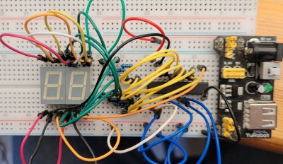
20220808_104304.jpg [ 544.96 KiB | Viewed 5702 times ]


Attachments:
dualhex7seg.zip [1.01 KiB]
Downloaded 64 times

_________________
don't count on me, i'm engineer (Animotion)
my arduino pages: http://rcarduino.de
Top
 Profile  
Reply with quote  
 Post subject: Re: Atf16v8, atf22v10
PostPosted: Tue Aug 09, 2022 12:16 am 
Offline
User avatar

Joined: Fri Dec 11, 2009 3:50 pm
Posts: 3346
Location: Ontario, Canada
willie68 wrote:
Meawhile i have done this without any other parts involved. Simply a ATF22V10C, 2 common anode 7-segmant displays, and 7 150Ohm resistors. works, the chip even get warm.
I haven't looked at the ATF22V10C specs, but the outputs are probably quite a lot stronger when pulling low than when pulling high. That suggests that you'd do "better" using common cathode displays. (I'm assuming you only use the parts you have on hand, and aren't willing to add a FET, a BJT or an IC to act as a buffer.)

But you've already gotten the project working, so maybe "better" doesn't matter! :P Common cathode displays will probably allow you to achieve the same brightness with higher resistor values (thus allowing the CPLD to run cooler), but.... :?:

-- Jeff

_________________
In 1988 my 65C02 got six new registers and 44 new full-speed instructions!
https://laughtonelectronics.com/Arcana/ ... mmary.html


Top
 Profile  
Reply with quote  
 Post subject: Re: Atf16v8, atf22v10
PostPosted: Tue Aug 09, 2022 4:45 am 
Offline
User avatar

Joined: Tue Nov 16, 2010 8:00 am
Posts: 2353
Location: Gouda, The Netherlands
willie68 wrote:
For me it's not clear, if the term:
IOS(1) Output Short Circuit Current VOUT = 0.5 V -130 mA
is the term per Output pin

The footnote (1) explains that short circuit current is only allowed for 1 pin at a time, and only for 30 seconds.


Top
 Profile  
Reply with quote  
 Post subject: Re: Atf16v8, atf22v10
PostPosted: Wed Aug 10, 2022 8:09 am 
Offline
User avatar

Joined: Wed Jul 27, 2022 6:14 am
Posts: 54
Dr Jefyll wrote:
willie68 wrote:
Meawhile i have done this without any other parts involved. Simply a ATF22V10C, 2 common anode 7-segmant displays, and 7 150Ohm resistors. works, the chip even get warm.
I haven't looked at the ATF22V10C specs, but the outputs are probably quite a lot stronger when pulling low than when pulling high. That suggests that you'd do "better" using common cathode displays. (I'm assuming you only use the parts you have on hand, and aren't willing to add a FET, a BJT or an IC to act as a buffer.)

But you've already gotten the project working, so maybe "better" doesn't matter! :P Common cathode displays will probably allow you to achieve the same brightness with higher resistor values (thus allowing the CPLD to run cooler), but.... :?:

-- Jeff

I have a lot of stuff here. FET, BJT or ULN2003/2803 are availble. But i haven't got enough 7-seg commen cathode displays...
:roll:
It was just a spare time project, until I found the bug in my 6502 SBC. Sometimes you just need a sense of achievement.

Arlet wrote:
willie68 wrote:
For me it's not clear, if the term:
IOS(1) Output Short Circuit Current VOUT = 0.5 V -130 mA
is the term per Output pin

The footnote (1) explains that short circuit current is only allowed for 1 pin at a time, and only for 30 seconds.

So, with the actual design i have max -80mA on average on the output col pins and 20mA on the other. (with all segments on) The chip is getting warm but not hot.
If i get the common cathode displays, i will use some kind of FET driver for the cols. (As i do this in my 3x3x3 cube)
Attachment:
20220809_073928.jpg
20220809_073928.jpg [ 306.66 KiB | Viewed 5584 times ]

_________________
don't count on me, i'm engineer (Animotion)
my arduino pages: http://rcarduino.de


Top
 Profile  
Reply with quote  
 Post subject: Re: Atf16v8, atf22v10
PostPosted: Wed Aug 10, 2022 10:44 am 
Offline
User avatar

Joined: Tue Nov 16, 2010 8:00 am
Posts: 2353
Location: Gouda, The Netherlands
willie68 wrote:
So, with the actual design i have max -80mA on average on the output col pins and 20mA on the other. (with all segments on) The chip is getting warm but not hot.


You're probably ok with that. The 80 mA has to go through the VSS pin, and the 20mA through the VDD. So, maximum peak current is the 80mA, well below the 130mA.

Note that the chip not getting hot isn't necessarily a sign that all is well. There will be very localized heating in the output driver, so it could very well overheat while the rest of the chip is still cool. High temperatures at the pad might lead to defects in the gold/aluminium transition layer, and cause damage over time.

https://en.wikipedia.org/wiki/Gold%E2%8 ... ermetallic


Top
 Profile  
Reply with quote  
Display posts from previous:  Sort by  
Post new topic Reply to topic  [ 7 posts ] 

All times are UTC


Who is online

Users browsing this forum: No registered users and 10 guests


You cannot post new topics in this forum
You cannot reply to topics in this forum
You cannot edit your posts in this forum
You cannot delete your posts in this forum
You cannot post attachments in this forum

Search for:
Jump to: