6502.org Forum  Projects  Code  Documents  Tools  Forum
It is currently Thu Apr 25, 2024 9:58 am

All times are UTC


Post new topic Reply to topic  [ 46 posts ]  Go to page Previous  1, 2, 3, 4  Next
Author Message
PostPosted: Sat Aug 06, 2016 6:23 am 
Offline
User avatar

Joined: Thu Dec 11, 2008 1:28 pm
Posts: 10793
Location: England
FPGA synthesis is not unlike an optimising compiler. Not many people actually read the compiler source or the code it produces. For a few people a closed source black box is an absolute disqualifier but for others it is an acceptable means to an end. HDL is pretty low level and your timing reports will tell you how the implementation is put together. Usually you can even get a gate level netlist out.

If you want open source tools you can use Lattice and IceStorm.


Top
 Profile  
Reply with quote  
PostPosted: Mon Aug 08, 2016 7:03 am 
Offline
User avatar

Joined: Fri Nov 09, 2012 5:54 pm
Posts: 1392
...Had some bad experiences with Lattice back in 2000.

Now to toss in X02.
For some reason, X02 ended up as an abandoned paper design.
The idea was to build a 6502 compatible TTL CPU without microcode,
what means just using logic gates, a state machine and multiplexers
for the instruction decoder\sequencer.
http://6502.org/users/dieter/x02/x02.htm

Block diagram of the mill:
Image
Nothing special in here.
IAL,IAH = bypass latches between external data bus and internal address bus
CGH,CGL = constant generators
TH,TL = temporary registers for address calculation
P = processor status registers
ID = input data latch
IR = instruction register

Wasn't aware, that Arlet's core already used such bypass latches when making up that architecture.
(When toying with prefetch mechanisms, one might feel a need to have some more of those latches.)

Instruction decoder\sequencer:
Image

The idea was to first to classify an instruction (instruction type and addressing mode), and to use quite a few logic gates for building a lookup table.
Then to tap into it by using multiplexers controlled by a state machine for generating the control signals for ALU, register read/write, flag write etc.
During the "data phase" of an instruction, it passes generation for a lot of those control signals over to a lookup table.

Some part of the state machine sequence diagrams:
Attachment:
x02_sm10.png
x02_sm10.png [ 40.71 KiB | Viewed 3111 times ]


When taking a look at all the variations of OR,AND,LDA, etc., the trick is, that a lot of instructions share the same sequence
for address calculation, just the part that handles the data operation is different.
Interesting thing is, that those nifty addressing modes break down into just a few little innocent looking boxes in the diagram,
for the NMOS 6502 (151 instructions) something like that would handle everything but BRK,RTS,RTI,JMP abs, JMP (abs),
PHA,PLA,PHP,PLP and the branches, in other words anything but 17 instructions,
and that would be 88.74% of the NMOS 6502 instruction set.

The branch instructions share the same sequence and just test different flags,
maybe the BRK sequence could be tricked into handling RES,NMI,IRQ too.

My advice here is not to see the 6502 instruction decoder\sequencer as a 'monolithic block', it can be broken into smaller chunks.
While implementing those chunks, it might be possible to use a mix of logic gates, lookup tables, state machines and\or microcode.
(Maybe chunks could be pipelined, too.)
It just depends on whether you want to optimize for speed or for compactness.

When writing good code for the 6502, the important thing is to have the right value at the right place in the right moment...
and how you accomplish this is going to be your problem.

The same thing pretty much seems to be true at hardware level when designing the mill of a CPU plus the instruction decoder\sequencer.

Please don't let dogma and school knowledge spoil your creativity. :)

;---

BTW: X02 had a one level pipeline.
In the cycle after an instruction fetch the Opcode has to be decoded, so the "key" to making it pipelined was to pre_emptively read a Byte
from the data bus to be used as data, or as the low_Byte for an address calculation.
A 74151 working as "predecoder" checked for one Byte instructions: $x8, $xA, $xB.
It prevented PC from getting loaded with PC+1 in this cycle, what effectively "discarded" the Byte that was fetched.

For the legal NMOS 6502 \ 65C02 instructions, this will do.
Technically, RTS and RTI are one Byte instructions, too. Out of paranoia I had checked them in X02, too...
what isn't necessarry, because those instructions would load PC with a new value after PC would have been incremented once too many.

;---

Just adding some pictures for the lookup table:
(empty = signal undefined, rectangle = signal active, slash = signal inactive)
// Lookup table isn't throughly checked for errors, you better build your own table.
Attachment:
x02_lt.zip [316.2 KiB]
Downloaded 91 times


Top
 Profile  
Reply with quote  
PostPosted: Mon Aug 08, 2016 11:07 am 
Offline
User avatar

Joined: Fri Nov 09, 2012 5:54 pm
Posts: 1392
Now for something different.

Imagine, there is a JMP instruction, and the CPU just reads the two address Bytes
for the target address into a 16 Bit register, let's say "DP" for "data pointer".

One trick would be, to place "DP" on the address bus when fetching the next Opcode,
then to increment the value and to write it into PC...
but this won't simplify having a fast response to interrupts.

Another trick would be swapping "DP" and PC.
If you have two registers with the inputs connected to the same bus,
and with the outputs connected to the same bus,
this could be done "in the background" by just swapping the control signals of both registers
without that there is any bus activity.

Image

// If you happen to have an idea how to efficiently do this with more than 2 registers,
// please post it here.

;---

Now let's suppose, that we have a loop like this:

Code:
     LDA #$20
     LDX #$00

foo: STA $0400,X ; 5 cycles
     INX         ; 2 cycles
     BNE foo     ; 3 cycles


Let's suppose, that adders are cheap.

We could have two registers, X+ and X-.
When X is loaded with a Byte (or when X is modified),
X+ is set to X+1 in the next cycle "in the background",
while x- is set to X-1.

Also, we could do a flag evaluation in the background.
INX/DEX modifies the N flag and the Z flag,
so we have NZ[x+] and NZ[x-].

If we happen to have a prefetch mechanism
(SDRAMs or fast synchronous SRAMs might give you a burst of 8 Bytes when reading them),
we could detect that INX instruction in advance, then to pull a trick that the code thinks
that X was incremented and that the flags were evaluated,
maybe by making use of the things mentioned above.

This might save the two cycles required for a "normal" INX,
speeding up that loop by 20%.

// BTW: 68010 hat a prefetch mechanism that was able to detect "tight loops".

;---

Well, there is INY\DEY...
where we could evaluate values "in advance" when Y is getting written/modified.

This brings up an interesting question: what about the accumulator ?

In the 65C02, the accumulator could be incremented/decremented, too.

When having "background registers" like A<, A>, maybe shifting could be done like this, too.

Rotating the accumulator would be a little bit more difficult, because the C flag would go
into the accumulator, and when rotating "in advance", we don't know what value the C flag
will have when the code running needs the result from that rotate...
Means we would need to evaluate a rotate in advance with assuming that C is 0,
and with assuming that C is 1, then to make use of the right result according
to the value that the C flag actually _has_ when the code "thinks" that a rotate
is supposed to be done.

When having a prefetch mechanism, and when having the Byte that goes into ADC or SBC from the bus...
just don't forget that D flag, which switches between binary and decimal mode. ;)

Also, we need to take into account, that caclulating the one or other thing
in advance "in the background" might take a cycle, so be sure that those
X+\x- etc. registers contain a valid result when making use of them.


Top
 Profile  
Reply with quote  
PostPosted: Mon Aug 08, 2016 11:59 am 
Offline
User avatar

Joined: Fri Nov 09, 2012 5:54 pm
Posts: 1392
"Prefetch mechanism" sounds simple, but could become very complicated.

In its simplest form, just a single instruction prefetch could be done like this:
When there is a read/modify/write instruction, like incrementing a Byte in memory,
there is a cycle where the 6502 internally is busy, so we could try to fetch
the next Opcode Byte there.

(If we would want to pre_fetch an Opcode in the second cycle of an instruction
like TAX, this could be done, but we would need to know if we really could
use this cycle when said cycle starts, what asks for a predecoder).

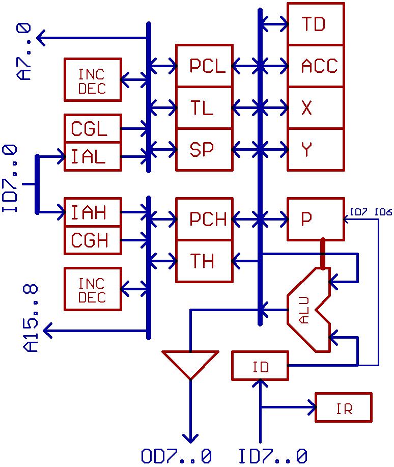
For a TTL CPU, placing a transparent latch in front of the instruction register
might be a nice idea, you just have to freeze it after a successful prefetch
until the instruction register has read it.

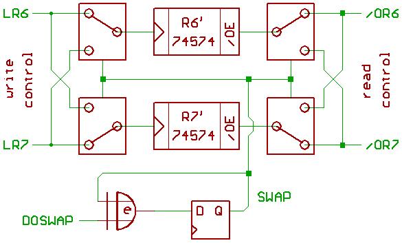
For a FPGA CPU, you probably would have two "instruction registers",
and tinker a bit with which register is getting read and which register
is getting written in which cycle.

What complicates things a bit is, that PC needs to be incremented after
successfully fetching an Opcode Byte, so you may need a register that
keeps the value of PC before PC is getting incremented in case
that the pre_fetched instruction has to be discarded if there is an interrupt
or such...

Actually, the game could be a little bit more complicated,
as "the devil always hides in the detail".
And I have to admit that I haven't dug too deep into it...
// the problem always was getting things working at all, not to increase speed.

;---

Of course, if we have SDRAM (or fast synchronous SRAM), and if we are always
reading 8 Bytes in a row, probably the most economical approach would be
to have 8 registers for pre_fetched Bytes, and "to tap into them" by using
multiplexers...
This brings back memories to my old TREX project:
http://www.6502.org/users/dieter/tarch/tarch_7.htm

But if we happen to have pre_fetched opcodes, to be able to make use of them
it would be nice to have some info about them in advance:
1) How many Bytes an instruction will take in total ?
2) Would the instruction need to read/write memory ? // that RDY signal, etc...
3) Would the instruction change program flow ? //Bxx, JMP,JSR

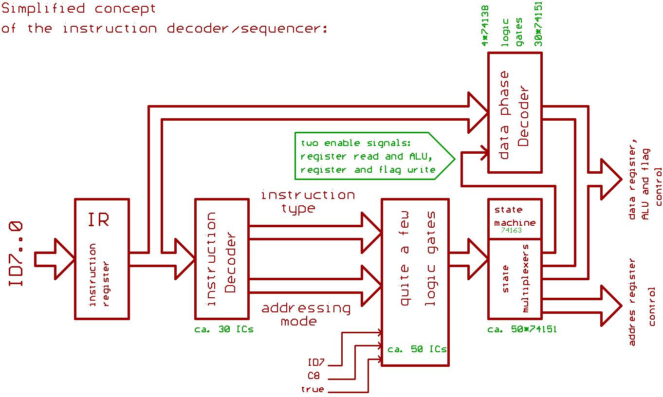
A predecoder basically tells the rest of the circuitry about some of that info,
but we would be going to need one predecoder per pre_fetched Byte.
Basically, a predecoder can be a lump of fast (and preferrably simple) logic gates,
for instance the NMOS 6502 already has a little predecoder, too.

Making correct use of that info in the right order will give you quite a headache...
at least it gave me a headache when building TREX... with 13 instructions in total.
Also, in a 6502, we probably can't instantly tell which of the pre_fetched Bytes
will be Opcode and which will be data...
and that's why every Byte would be going to need its own predecoder.

The deeper the CPU pipeline, the stronger the effect of a change in program flow...
in other words, a CPU with a very deep pipline might be fast indeed
...while having the maneuverability of a super tanker. :)

Of course, one could try to calculate the target address of a conditional branch
taken in advance, then try to evaluate the instructions "at both sides of the fork"
in advance, but it's going to be tricky stuff, and having interrupts won't make
things any better.

// I don't have any practical experience in that field, this _really_ is half_baked stuff.

A change in program flow just has this habit that the ALU (and\or the other computational blocks)
of your CPU might be sitting idle for some cycles in the worst case...

If I remember correctly:
To compensate for this, SHARC DSPs have the "normal" calls and returns...
plus _delayed_ calls and returns.
If there is a delayed return in the program flow, the next few instructions
in the code are going to be executed before the return actually takes place.
...but this won't be 6502 compatible. :)


Top
 Profile  
Reply with quote  
PostPosted: Mon Aug 08, 2016 12:31 pm 
Offline
User avatar

Joined: Fri Nov 09, 2012 5:54 pm
Posts: 1392
...What brings us to another neat concept.

http://www.innovasic.com/products/product-literature

The Fido1100 microcontroller has a CPU32 core (that's 68020 minus a few addressing modes).

And the problem with the 68000 family is, that the CPU has a lot of registers,
which have to be saved on stack when there was an interrupt,
and which have to be restored from stack after the interrupt service routine did its job.

Fido1100 has 5 sets of CPU registers (including the status registers I think),
so if there is an interrupt there is the possibility to just switch to another
register set within one clock cycle without the need for saving/restoring registers...
then to switch back.

BTW: all 5 register sets show up in the peripheral address range,
just to make sure you propperly could initialize tham and such...

We could imagine, that pulling a similar trick might be possible for our 6502.

;---

Now let's suppose, that we would like to build a game system,
and that we would like to run certain chunks of code in certain raster lines...

We could switch to another register set if there was an interrupt,
run a thread from the registers there, then to have an instruction to switching back.
If we would have a reconfigurable lookup table to assign certain threads to certain
interrupt sources on the fly, maybe this would be interesting...

No need to save/restore registers and to check for the interrupt source.

;---

Of course, if we have more than one register set, and if the ALU would be sitting
idle for some cycles because of pipeline stalls etc., it might become interesting
if the instruction decoder\sequencer would be able to "juggle" between tasks\threads
to prevent the ALU from "running dry".

Hey, if we would be trying to run something like a web browser on that CPU later,
there sure would be more than one task\thread running at once:
For instance TCP\IP stack plus *.png to *.bmp conversion. ;)

;---

For deeper pipelines, it feels like the complexity of the control circuitry
exponentially grows with pipeline depth, and having an 8 level deep pipeline
sure would be a nightmare to design...

But wait: there is the "Barrel Processor" concept.
We probably would have just one ALU and one instruction decoder\sequencer
(ok, I'm over_simplifying things a lot here), and they are deeply pipelined,
but since we have a lot of register sets, we simply could "cycle" through
the register sets while making use of the pipeline...

So it just still would be one processor, but to the "end user",
the CPU would just look like a multi_core CPU.

Maybe it would look a little bit like XMOS xCORE... or like Parallax Propeller...
just kidding. :)


Top
 Profile  
Reply with quote  
PostPosted: Mon Aug 08, 2016 12:56 pm 
Offline
User avatar

Joined: Fri Nov 09, 2012 5:54 pm
Posts: 1392
When I was building TTL CPUs, memory always was faster than it needed to be.
// Means, the text to follow certainly is less than half_baked. :lol:

But when using a FPGA, the CPU might become faster than the RAM.

6502 has a 64kB address range, and it would be nice if 64kB would fit into the FPGA...
program memory preferably arranged in 8 or more blocks for feeding that prefetch mechanism.
Data memory maybe still could be 8 Bit... except for zero page and stack area.

In theory, maybe you could go "Harvard", what means separate memory for instruction and data,
(even for external memory maybe), as long as this _stays_ fully transparent to the "end user".
Just make sure that executing code from data memory still is possible (by sacrificing speed),
and that data reads\writes from\to program memory still are posssible (by sacrificing speed).
...Then to take a little bit care when writing your code about where data and code will end up in memory.

If there isn't enough RAM in the FPGA, external RAM is required, and external RAM
probably would be slower than the CPU, so "CPU cache" might become a topic...
a topic where I'm having little to no knowledge. :oops:

To make it short: a CPU cache is sort of a kludge to compensate for missing RAM speed.
Kludges just have that habit to give you a headache sooner or later... ;)

;---

To make a short list:

Instruction cache makes sense, but you need to consider that program memory could be written
in the RAM, either by the CPU... or by another CPU in a multiprocessor system,
and in that case the instruction cache needs to be flushed.
Also, freezing the instruction cache might be useful when running a time critical block of code.
(Did this with the 68020.)

Data cache is evil, because you need to consider that the CPU writes back to memory,
and that external memory and data cache are supposed to stay consistent.
Also, you may want to have some part of data memory _uncached_...
...mainly because caching the registers of a 6522 timer doesn't make sense.

This was the short form, and things might be getting more evil when a MMU becomes part of the game.


Top
 Profile  
Reply with quote  
PostPosted: Mon Aug 08, 2016 1:13 pm 
Offline
User avatar

Joined: Fri Nov 09, 2012 5:54 pm
Posts: 1392
My "bag of odd ideas" now nearly is empty, just one more thing:

If you can't afford to have the propagation delay of a 16 Bit carry chain
when building a TTL or transistor CPU, there is the carry skip adder concept:
https://en.wikipedia.org/wiki/Carry-skip_adder

PC is a 16 Bit register, formed by two 8 Bit registers: PCL, PCH.
So when incrementing the 16 Bit PC, we could calculate PCL+1 and PCH+1 in parallel...
to have PCH+1 at the ready.

If there is no carry from out of PCL+1, we take PCH as PCH in the next cycle,
if there is a carry, we take PCH+1.

;---

Sounds simple...
but there are those conditional branch instructions which have a signed 8 Bit offset.

Let's name the uppermost Bit of that offset ID7 (input data),
and the carry output from PCL + offset C8.

The traditional way would be to sign extend the offset to 16 Bit, then to add it to PC
(like I did in my M02 CPU.)

Another trick would be to calculate PCH+1 and PCH-1 in parallel with PCL + offset.
Then to select the value for PCH in the next cycle according to ID7 and C8:

C8=0, ID7=0 -> PCH:=PCH
C8=0, ID7=1 -> PCH:=PCH-1
C8=1, ID7=0 -> PCH:=PCH+1
C8=1, ID7=1 -> PCH:=PCH

To make it short: PCH doesn't need to be incremented/decremented if C8 XOR ID7 = 0.


Top
 Profile  
Reply with quote  
PostPosted: Mon Aug 08, 2016 2:11 pm 
Offline
User avatar

Joined: Fri Nov 09, 2012 5:54 pm
Posts: 1392
Recommended reading:

Microprocessor Logic Design
Nick Tredennick
Digital Press, 1987
ISBN 0-932376-92-4
(The author did microcode and logic design for the 68000.)

Journal of Microprocessing and Microprogramming
1982\10\163
1987\20\235
(A little bit info related to the 6800 and 68000 instruction decoder\sequencer.)


...It also would be a nice idea to pay the library of the computer science department
of your nearby university a visit, just to ask if they might happen to have the
"Journal of Microprocessing and Microprogramming" and the "IBM Research and Development Journal"
on stock in printed form... and what else they happen to have on stock.

;---

If you made it to build your own superscalar, multithreading 6502 running at Pentium speed,
please post a good set of technical documentation about its innards,
so that other hobbyists could build on the things that succeeded...
and on the things that failed.

Try to keep in mind, that the Pentium had evolved out of an obscure 4 Bit calculator chip...
and that there is a joke that about 80% of the transistors inside a Pentium are just there
for providing some backwards compatibility to said chip. ;)

Had my say, and I'm looking forward to see what the community can make out of this mess.
Feel free to add to "the pool of half_baked obscurities" for speeding up a 6502. :)


Top
 Profile  
Reply with quote  
PostPosted: Mon Aug 08, 2016 2:38 pm 
Offline

Joined: Sat Mar 27, 2010 7:50 pm
Posts: 149
Location: Chexbres, VD, Switzerland
Wow, this is probably very interesting but definitely too long for me to read all this (at least for now). Could you please summarize a little ?

The conclusions we reached in other threads talking about applying technics such as superscalar design and pipelineing to 6502 is that all relies on the cache. Unlike RISC CPUs, the 6502 was designed so that it access memory on every cycle - heck there is even no way of not accessing memory on the 6502 bus ! - and it uses most of those cycles. The obvious way to fasten the 6502 is to remove useless cycles, (which are often because the ALU has to do a 16-bit operation in 2 steps), so that the 6502 do only useful memory access.

For example, ROL and ROR, LSR and ASL ZP instructions can be optimized to be 4 cycles instead of 5, PHA, PHP and PLA, PLP can be optimized to be only 2 cycles instead of 4/3, JSR can me made to be 5 cycles instead of 6, etc...

Then the memory is accessed on every cycle, so the only way to speed up the processor is to have either an instruction cache or a data cache, or both. Because the 6502 has no IN/OUT instructions, it uses memory mapped registers, so the caches has to be built in order to know which adresses are memory mapped, and never cache them. The problem of building instruction cache or data cache is in itself large and there is so many options it is not possible to come up wtih one "ideal" answer.

Should instructions, data, or both be cached? If both, should data and instruction cache be unified as a single memory with multiple read ports, or as separate memories? How much memory is reasonable for them? Is is better to have a very reliable cache (a complex algorithm creating a low miss rate), but that needs a couple of cycles to fetch any data (requires an adequacy large sized pipeline), or a poorly performant cache using a trivial algorithm (such as direct mapped), but that can provide data in 1 cycle when the data is cached? Should the CPU run on the same clock as the bus, or can it run faster? If a data cache is present, does it always writeback data to the bus on bus writes (write-through), or does it simply update the cache, leaving wrong data lie in memory until the cache line is flushed?

How long should the cache lines be? Is it better to have some meachanism that ensure that zero page and/or stack page are always cached, or instead is it better to have a tiny cache, and let the most used adresses "naturally" get cached, no matter whether those are in zero page or not ? How are self-modifying code handled with the cache? Is it worth adding a lot of hardware just to maintain compatibility? If zero-page is hard-wired into the data cache, how is executing code from zero-page supported? (same applies to stack page).

There is no universal answer to all those questions, and you'll have to answer them in order to design a pipelined 6502 - I didn't even mention anything more advanced like dynamically scheduled or superscaler which in themselves are huge and complex problem that applies poorly to 6502 - but just a pipelined one is already a huge question, which relies almost entierely on cache.

It also depends whether you want the external bus to be 6502 compatible (with A0...A15, D0..D7, R/W and M2 lines) or not. I feel it should remain 6502 compatible, but the cache should also be configured to know which adresses are memory mapped I/O and which aren't.


Top
 Profile  
Reply with quote  
PostPosted: Mon Aug 08, 2016 2:54 pm 
Offline
User avatar

Joined: Fri Nov 09, 2012 5:54 pm
Posts: 1392
Quote:
Wow, this is probably very interesting but definitely too long for me to read all this (at least for now).
Could you please summarize a little ?

Tried to do this a bit in my first posting in this thread... :oops:

Quote:
The conclusions we reached in other threads talking about applying technics such as superscalar design
and pipelineing to 6502 is that all relies on the cache. Unlike RISC CPUs, the 6502 was designed so that it
access memory on every cycle...

That yes... but what, if the CPU has a 64kB address range, if the FPGA internally has 32kB RAM or more
(organized in 2kB blocks), and if you intentionally go without a cache by keeping the code and the data
that really has to be fast inside the FPGA RAM blocks ? ;)

BTW:
I have no "academic degree" in computer science, I'm only a hobbyist who had built some TTL CPUs
and a transistor CPU many years ago. And I don't think that _all_ of my ideas above might be good...
or 100% technically correct :)


Top
 Profile  
Reply with quote  
PostPosted: Mon Aug 08, 2016 6:04 pm 
Offline

Joined: Tue Jul 24, 2012 2:27 am
Posts: 672
Regarding your prefetching idea, one thing I didn't see addressed is dirtying the prefetched values. In self-modifying code, the self modifications many times write to the next instruction being executed. Any next-instruction or 8-byte prefetch could be loading in stale data if pulled before that write instruction finished.

_________________
WFDis Interactive 6502 Disassembler
AcheronVM: A Reconfigurable 16-bit Virtual CPU for the 6502 Microprocessor


Top
 Profile  
Reply with quote  
PostPosted: Mon Aug 08, 2016 8:06 pm 
Offline

Joined: Sat Mar 27, 2010 7:50 pm
Posts: 149
Location: Chexbres, VD, Switzerland
I should add that I personally didn't like too much FPGA coding, because it tend to be based on closed source stuff that is not long-term maitainable. For example, using a board whose support will end in 5 years is not acceptable to me.

I think it would be funnier to use Logisim or any other digital electronic simulator. If your goal is to actually get something running on FPGA then sure go ahead, but instead if the goal is to see how it is possible to do enhanced 6502 architectures just for fun then it sounds like too much of a hassle.

I do not know how much SRAM is packed with FPGA, but you will have to remember that :
  • You might want to keep some of it free for other usages
  • The cache will have to be duplicated for every read port. It would not be stupid to have a cache with 4 or 5 read ports, so for example 2kb of cache turns out to be 40 kb if there's 5 read ports.
  • Extra SRAM is probably needed to have the cache line state, i.e. "valid", "invalid", and which memory area is currently loaded. The more complex the cache, the more SRAM will be needed here, sometimes almost as much as the cache data itself (and yes, cache state might also need duplication for each read port).
  • If performance is your only worry, then stop thinking about an ehanced 6502 right now. It's more an intellectual exercice, thus "use everything as cache" is a bit cheating :)


Top
 Profile  
Reply with quote  
PostPosted: Sun Aug 14, 2016 7:06 am 
Offline
User avatar

Joined: Thu Dec 11, 2008 1:28 pm
Posts: 10793
Location: England
Lots of ideas here - thanks for sharing them! It is always a lot to digest when someone has thought about something for a length of time - there's a lot of context to be constructed.

There are two books on my shelf which are I think worth recommending:
Tanenbaum's "Structured Computer Organisation"
Hennessy& Patterson's "Computer Architecture, A Quantitative Approach"

While I did devour the first, I confess I have not managed to do the same with the second. I'm certain that it's well worth understanding various existing approaches, if the aim is to make something splendid - reading the HDL of existing cores would be one way. The aim is to understand the microarchitecture: busses, latches, flops, pipeline stages if any. This is where a good diagram is worth a huge amount.

(If the aim is just to make a working CPU, then it's possible to dive in. But that first attempt may not be a good starting point to make a high performance CPU, so a second attempt should be a fresh start.)

For myself, thinking about high performance 6502, which is of course an odd thing to do, I would be inclined to start with building and understanding a modern pipelined RISCy machine, and then considering how to make it into a 6502. It will not be a good fit! But to take a 6502 implementation and then trying to give it a deep pipeline, that seems to me more difficult. Of course, this gut feeling of mine could be wrong.

For sure, in any case, it's important to consider what the implementation technology is. A TTL machine, an EPROM-based machine, an FPGA machine, are going to have different constraints and end up with different characteristics. Within an FPGA, you won't get a terribly high clock speed if you don't have some idea of a clean microarchitecture.


Top
 Profile  
Reply with quote  
PostPosted: Tue Sep 06, 2016 10:37 am 
Offline
User avatar

Joined: Thu Dec 11, 2008 1:28 pm
Posts: 10793
Location: England
[placeholder, hoping to start a discussion on fused ops]


Top
 Profile  
Reply with quote  
PostPosted: Tue Sep 06, 2016 6:49 pm 
Offline

Joined: Sat Jan 04, 2003 10:03 pm
Posts: 1706
ttlworks wrote:
BTW: when trying to build sort of a game system nowaday,
for a colored screen resolution of 640*480 or more I think that a 64kB address range
won't do, so there is that proposal for giving a 6502 a 24 Bit address bus... ;)


You might as well just go for the 65816. The 6502 literally has no advantages for everything described above.

ttlworks wrote:
;---

About the 65816:

SPI would be nice, too... maybe in combination with MVP and MVN. ;)


If you build an SPI controller with 256 bytes of "transceive" space, you can use MV* to transfer blocks of data up to 256 bytes in length before having to adjust pointers and the like.

ttlworks wrote:
It's annoying that the addresses of the 'native mode' interrupt vectors
conflict with the jump vector table of the Commodore kernal,
but I'm not sure how to give the 65816 something similar to the
VBR (vector base register) from the 68020.


68010 actually.

You can easily implement a VBR yourself if you're up for a bit of soldering.

Step 1: Implement a 12-bit register to serve as the VBR in I/O space for your platform. Assuming that you're intending to run Commodore Kernal as your BIOS, this register will obviously need to be configurable from emulation mode before the CPU enters native mode. In fact, I would go the whole way and implement this register as a 20-bit register, so that you can move the vector table clean outside of bank 0 all-together if you want. Remember that the vectors still refer to bank-0 procedures, though.

Step 2: Create a circuit which places the contents of this VBR onto address bits A23-A4 when the signal VPB is asserted, thus completely ignoring whatever the CPU is driving them with (which is guaranteed to be in bank 0, BTW). VPB will go low when the CPU is busy fetching an interrupt vector, and return high after it's done.

Step 3: Leave A3-A0 as-is, thus letting the CPU select the desired interrupt vector.

OR, you can do what the Apple IIgs does, which places one of five (I think?) vectors on the data bus in response to monitoring VPB and A2-A0.

There is historical precedent for this: WDC's own microcontrollers implement a similar circuit under the hood, Apple IIgs intercepts vector pulls, etc.

In fact, between ABORTB and VPB, you have everything you need to implement user- and supervisor-modes of operation including virtual memory without needing a separate CPU (as the early Suns did back when they used 68000s).

ttlworks wrote:
I'm not sure, if the 6502 needs a 'multiply' instruction,
as most of the code probably won't make use of it.


Only because nobody has had one available before. If one were available, you bet I'd use the heck out of it.


Top
 Profile  
Reply with quote  
Display posts from previous:  Sort by  
Post new topic Reply to topic  [ 46 posts ]  Go to page Previous  1, 2, 3, 4  Next

All times are UTC


Who is online

Users browsing this forum: Proxy and 3 guests


You cannot post new topics in this forum
You cannot reply to topics in this forum
You cannot edit your posts in this forum
You cannot delete your posts in this forum
You cannot post attachments in this forum

Search for:
Jump to: