6502.org Forum  Projects  Code  Documents  Tools  Forum
It is currently Sun Apr 28, 2024 9:08 am

All times are UTC


Post new topic Reply to topic  [ 56 posts ]  Go to page Previous  1, 2, 3, 4  Next
Author Message
PostPosted: Sun Jan 01, 2017 2:20 am 
Offline
User avatar

Joined: Sun Dec 29, 2002 8:56 pm
Posts: 449
Location: Canada
I got slightly further with the project, but I don't have a C64 to test with. The last thing I did was create a board layout for something compatible with a VIC-II socket. I'm not sure how the board would fit. It may require adjusting the surrounding tin shielding.
Attachment:
FAL6567i.png
FAL6567i.png [ 34.9 KiB | Viewed 8181 times ]

This project was really for a chip equivalent to the 6567 for existing systems. It's possible these days to fit an entire C64 compatible into an FPGA. One of the generic existing FPGA boards could be used for that purpose. I've built several SoC's which are more high-powered than the C64 for the Nexys4ddr board for instance.

_________________
http://www.finitron.ca


Top
 Profile  
Reply with quote  
PostPosted: Mon Jan 02, 2017 12:02 pm 
Offline

Joined: Wed Mar 02, 2016 12:00 pm
Posts: 343
Looks like a fine replacement board! I have a C64 somewhere in my basement, I can check the dimensions tonight if you want me to.

My original idea was actually to use a CPLD for interfacing a 65C02 to a Vic-20 (based on a previous project which did so using discrete logic). At first I didn't think of making a C64 expansion for it, it was more of having a 40-col VGA output (for terminal), but with your nice 6567-core it might actually be worth a try to get C64-compatible graphics (I have no need for sound at the moment). I also want to allow for DIP 6502 (externally) to keep unintentional opcode compatibility as an option. For now I am only running Arlets original 6502 + RAM internally in the CPLD (I will add external DRAM later).

Oh, and I am using Lattice CPLD (code is usually 95%+ similar though).


Top
 Profile  
Reply with quote  
PostPosted: Mon Jan 02, 2017 12:25 pm 
Offline
User avatar

Joined: Thu Dec 11, 2008 1:28 pm
Posts: 10793
Location: England
Which Lattice part are you using kakemoms, and how much on-chip RAM does it offer?


Top
 Profile  
Reply with quote  
PostPosted: Tue Jan 03, 2017 9:21 pm 
Offline

Joined: Wed Mar 02, 2016 12:00 pm
Posts: 343
The metal box seems to be around 70x80mm, but if you look at pictures on the net, the VIC-II chip seems to be placed at different positions depending on the version of the board. So you may want to buy one before you decide on a layout.

I use a MachXO3 CPLD. There isn't much RAM in it, so a more permanent solution will be to add SRAM (but things take time). I think you can get them with up to around 64KB memory, depending on what you put inside.


Top
 Profile  
Reply with quote  
PostPosted: Wed May 31, 2017 9:06 pm 
Offline

Joined: Wed Mar 02, 2016 12:00 pm
Posts: 343
Rob Finch wrote:
I got slightly further with the project, but I don't have a C64 to test with. The last thing I did was create a board layout for something compatible with a VIC-II socket. I'm not sure how the board would fit. It may require adjusting the surrounding tin shielding.
Attachment:
FAL6567i.png

This project was really for a chip equivalent to the 6567 for existing systems. It's possible these days to fit an entire C64 compatible into an FPGA. One of the generic existing FPGA boards could be used for that purpose. I've built several SoC's which are more high-powered than the C64 for the Nexys4ddr board for instance.


I may try to implement this FAL6567 in a MachXO3 with more outputs for the RGB (about 6 per pin). While drawing the schematics I noticed that pin 9 here is connected to ground. Please note that some modern VGA cables have +5V on pin 9. It may not be of any concern since a monitor probably doesn't supply anything on pin 9 (unless you connect it to something else with +5V on pin 9). I will leave it unconnected just in case.


Top
 Profile  
Reply with quote  
PostPosted: Sat Nov 04, 2017 8:15 am 
Offline

Joined: Wed Mar 02, 2016 12:00 pm
Posts: 343
To follow up; The MachXO3 was not up to the task of running this core, so I ended up making my own implementation (of a 6560) for VGA. My core doesn't have sprites so its much simpler.

Just a question: Do you have to run this core at 1200MHz? It seems excessive. Some documentation would also be helpful.


Top
 Profile  
Reply with quote  
PostPosted: Sun Nov 05, 2017 4:56 am 
Offline
User avatar

Joined: Sun Dec 29, 2002 8:56 pm
Posts: 449
Location: Canada
Quote:
Just a question: Do you have to run this core at 1200MHz? It seems excessive. Some documentation would also be helpful.

The core does not have to be run at 1200MHz using 33MHz might be okay. The current timing generator multiplies the 14.31818MHz input clock by 66 to use a 945 MHz clock as the base timing unit. This clock is then divided by 28 to get a 33.75MHz clock. The reason to use a 33.75MHz clock is that when it's divided by 33 (1.0227MHz)it very similar to the original operating frequency of the C64. 33.750MHz is also close to the required clock for the VGA mode. It's probably possible just to use a 33MHz clock as the base clock rather than 945MHz. But then the timing for some games and other software might be off. Changing the clock rate of the C64 may change the power consumption. I'm not sure how flexible a C64 is when it comes to modifying the clock rate.

I've modified the board to latch some output bits in order to increase the number of bits available for color. But I've may not have posted this change yet.
Still on the back burner.

_________________
http://www.finitron.ca


Top
 Profile  
Reply with quote  
PostPosted: Mon Nov 06, 2017 3:14 pm 
Offline
User avatar

Joined: Wed Aug 17, 2005 12:07 am
Posts: 1207
Location: Soddy-Daisy, TN USA
FYI, I have several different C64's. I would be happy to offer any kind of help. I have an older "breadbin" C64 (NTSC), a C64C (much newer) and even a PAL C64.

Also, I have several C128's and a C128-D that also used the VIC-II.

_________________
Cat; the other white meat.


Top
 Profile  
Reply with quote  
PostPosted: Fri Dec 08, 2017 7:13 am 
Offline

Joined: Fri Dec 08, 2017 7:09 am
Posts: 1
What is the current status of 6567 core? How it's currently compatible with real 6567? I'm thinking to use this core in FPGA64 project which has so-so quality of VIC-II model.


Top
 Profile  
Reply with quote  
PostPosted: Sun Dec 10, 2017 3:56 am 
Offline
User avatar

Joined: Sun Dec 29, 2002 8:56 pm
Posts: 449
Location: Canada
Still needs some serious testing. It hasn't been run in anything except the simulator. There's bound to be bugs yet. The core has a mode that allows it to support more sprites (in theory) in a real C64. So the timing may be off as a result. The core is made around the idea of interfacing to a real C64, so it has bus output that should be compatible. But if you are making the core for an FPGA board this kind of bus interface might not be the best.

_________________
http://www.finitron.ca


Top
 Profile  
Reply with quote  
PostPosted: Tue Feb 27, 2018 11:41 am 
Offline

Joined: Wed Mar 02, 2016 12:00 pm
Posts: 343
Rob Finch wrote:
Quote:
Just a question: Do you have to run this core at 1200MHz? It seems excessive. Some documentation would also be helpful.

The core does not have to be run at 1200MHz using 33MHz might be okay. The current timing generator multiplies the 14.31818MHz input clock by 66 to use a 945 MHz clock as the base timing unit. This clock is then divided by 28 to get a 33.75MHz clock. The reason to use a 33.75MHz clock is that when it's divided by 33 (1.0227MHz)it very similar to the original operating frequency of the C64. 33.750MHz is also close to the required clock for the VGA mode. It's probably possible just to use a 33MHz clock as the base clock rather than 945MHz. But then the timing for some games and other software might be off. Changing the clock rate of the C64 may change the power consumption. I'm not sure how flexible a C64 is when it comes to modifying the clock rate.

I've modified the board to latch some output bits in order to increase the number of bits available for color. But I've may not have posted this change yet.
Still on the back burner.


I have been thinking a little bit about this. Have you thought about generating the clock on-chip, and only use the external clock as a sync for external DRAM/6510 access (via FIFO)?


Top
 Profile  
Reply with quote  
PostPosted: Sun Mar 04, 2018 7:43 am 
Offline
User avatar

Joined: Sun Dec 29, 2002 8:56 pm
Posts: 449
Location: Canada
Quote:
I have been thinking a little bit about this. Have you thought about generating the clock on-chip, and only use the external clock as a sync for external DRAM/6510 access (via FIFO)?

The FPGA requires an external clock source which is available on board. I don't think there's a frequency reference built into the FPGA. If the design were to be made entirely on one board an external clock source would be required. It's easier to just start with the one that's already there. Synchronizing with an external clock requires clock domain crossing logic and using fifo's might affect software compatibility. A lot of software depends on exact VIC timing. Another reason to have the systems clock available is for generating composite video which requires an accurate clock.

There are some extra logic resources available in the FPGA beyond what's required to implement a VIC-II compatible core. So I'm wondering what the extra logic resources could be used for ? One possibility I've thought of is more timer's / event generators. Or maybe floating point ?

_________________
http://www.finitron.ca


Top
 Profile  
Reply with quote  
PostPosted: Mon Mar 05, 2018 8:06 am 
Offline
User avatar

Joined: Sun Dec 29, 2002 8:56 pm
Posts: 449
Location: Canada
After scouting out some C64's to test with, I got to wondering if I could build a 6567 VIC-II test computer myself. It might be lower cost than a working vintage C64. And it would have almost all new parts. I've come up with a couple of circuits but they use a lot of IC's and I'm looking for something simple. I'm wondering if it could be interfaced to a micro-controller of some kind. Looking for suggestions here.

_________________
http://www.finitron.ca


Top
 Profile  
Reply with quote  
PostPosted: Mon Mar 05, 2018 9:39 am 
Offline
User avatar

Joined: Thu Dec 11, 2008 1:28 pm
Posts: 10793
Location: England
Are you aware of Grant Searle's minimal designs?
http://searle.hostei.com/grant/

There are of course others.


Top
 Profile  
Reply with quote  
PostPosted: Mon Mar 05, 2018 9:55 pm 
Offline
User avatar

Joined: Sun Dec 29, 2002 8:56 pm
Posts: 449
Location: Canada
Quote:
Are you aware of Grant Searle's minimal designs?
http://searle.hostei.com/grant/

Yes, Grant has some excellent designs.

A C64-like computer was designed for a test rig. The system will be composed of a least two circuit boards. The free cad toolset is limited to boards that are 3” x 4” and everything won’t fit on one board. The boards will be connected with a 50-pin connector.
A 14.318MHz oscillator is used for the color clock. A 32.768MHz oscillator is divided by four to generate an 8.192 MHz dot clock signal. This signal is slightly off the required 8.182 MHz signal, but color output isn’t being used so this is probably okay. Otherwise it would be a pita to generate the 8.18MHz clock. The VIC-II chip generates the PHI02 clock for the system.
The board only uses the sync and luminance outputs of the VIC-II chip since a VGA replacement will be used. Composite video out is only needed to verify the circuit works with a 6567.
A 65C22 is used to supply the high order address lines for when the VIC-II has control of the bus.
Three transparent latches are used to latch the row and column address from the VIC-II to generate an address for the static RAM (on the cpu board).
All the parts are low power CMOS except for the 6567.
Attachment:
File comment: Video board for test computer
Test6567Sch.png
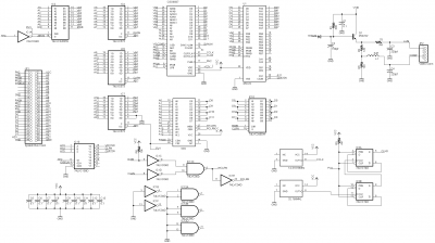
Test6567Sch.png [ 34.97 KiB | Viewed 7767 times ]

_________________
http://www.finitron.ca


Top
 Profile  
Reply with quote  
Display posts from previous:  Sort by  
Post new topic Reply to topic  [ 56 posts ]  Go to page Previous  1, 2, 3, 4  Next

All times are UTC


Who is online

Users browsing this forum: No registered users and 8 guests


You cannot post new topics in this forum
You cannot reply to topics in this forum
You cannot edit your posts in this forum
You cannot delete your posts in this forum
You cannot post attachments in this forum

Search for:
Jump to: