6502.org Forum  Projects  Code  Documents  Tools  Forum
It is currently Thu Apr 25, 2024 12:19 pm

All times are UTC


Post new topic Reply to topic  [ 41 posts ]  Go to page Previous  1, 2, 3  Next
Author Message
PostPosted: Sat Nov 22, 2014 12:29 am 
Offline

Joined: Mon Mar 02, 2009 7:27 pm
Posts: 3258
Location: NC, USA
MichaelM wrote:
... Also, keep in mind that I'm trying to keep the M65C02A as standard as possible in order to make use of available tools such as assemblers, compilers, and interpreters. Access to the features enabled by the prefix instructions will likely lag until someone (probably not me) adds the new instructions to a tool..

Michael, I just wanted to say hello and nice work on your specialized Forth M65C02A Core so far.
6502.org members Bitwise and teamtempest (TT) have helped greatly by adapting both of their assemblers for the 65Org16...
They are the bridge to the success of new 6502-like cores!

_________________
65Org16:https://github.com/ElEctric-EyE/verilog-6502


Top
 Profile  
Reply with quote  
PostPosted: Sat Nov 22, 2014 7:10 am 
Offline
User avatar

Joined: Sun Jun 30, 2013 10:26 pm
Posts: 1925
Location: Sacramento, CA, USA
MichaelM wrote:
... Perhaps I've missed something obvious, so I'm looking to you, Jeff, and others to clear up any misconceptions that I've had while working to determine the best instructions to design and implement to support a FORTH VM with the M65C02A.

From Brad's website and the Heart of FORTH page, the three core operations of a DTC/ITC FORTH inner interpreter are defined as shown below:
Code:
             ITC                                     DTC
================================================================================
NEXT:   W      <= (IP++) -- Ld *Code_Fld     ; W      <= (IP++) -- Ld *Code_Fld
        PC     <= ((W))  -- Jump Dbl Indirect; PC     <= (W)    -- Jump Indirect
================================================================================       
ENTER: (RSP--) <= IP     -- Push IP on RS    ;(RSP--) <= IP     -- Push IP on RS
        IP     <= W + 2  -- => Param_Fld     ; IP     <= W + 2  -- => Param_Fld
;NEXT
        W      <= (IP++) -- Ld *Code_Fld     ; W      <= (IP++) -- Ld *Code_Fld
        PC     <= ((W))  -- Jump Dbl Indirect; PC     <= (W)    -- Jump Dbl Ind
================================================================================         
EXIT:   
        IP    <= (++RSP) -- Pop IP frm RS    ; IP     <= (++RSP)-- Pop IP frm RS
;NEXT
        W      <= (IP++) -- Ld *Code_Fld     ; W      <= (IP++) -- Ld *Code_Fld
        PC     <= ((W))  -- Jump Dbl Indirect; PC     <= (W)    -- Jump Dbl Ind
================================================================================         

Er, be careful, Michael! ITC and DTC, as I understand them, have one less level of indirection than I believe that you're implying in the examples above.

The way that I understand ITC NEXT, it is a JMP ((IP++)), with W acting as an intermediate pointer.
From Brad's Moving Forth Part 2 page:
Code:
ITC-NEXT:       LDX ,Y++        ; (8) (IP)->W, increment IP
                JMP [,X]        ; (6) (W)->temp, jump to adrs in temp

The way that I understand DTC NEXT, it is a JMP (IP++).
From Brad's Moving Forth Part 2 page:
Code:
DTC-NEXT:       JMP [,Y++]      ; (9) (IP)->temp, increment IP, jump to adrs in temp
                                ;     ("temp" is internal to the 6809)

The way that I understand STC NEXT, it is a JMP (S++), otherwise known as RTS.
[Edit: Oops, that's wrong! RTS is STC-EXIT, and there is no STC-NEXT! ... at least that's my understanding ...
So, to summarize,
ITC's IP holds the address of the address of the value to be loaded into PC;
DTC's IP holds the address of the value to be loaded into PC;
STC's IP is the value of PC; they are one and the same register.]

The 8-bit 6502 versions get cluttered by the double-width increments and such, so it's easier to see what's actually happening with 6809 snippets. My 65m32 versions look almost identical to the 6809 versions, so I'll spare you the details (you've probably already seen them earlier anyway).

Mike


Last edited by barrym95838 on Sun Nov 23, 2014 3:29 am, edited 1 time in total.

Top
 Profile  
Reply with quote  
PostPosted: Sat Nov 22, 2014 1:15 pm 
Offline
User avatar

Joined: Mon Apr 23, 2012 12:28 am
Posts: 760
Location: Huntsville, AL
Mike:

Thanks very much for reading the post and replying. As before, you are correct there are too many parentheses in the pseudo code. Please see the following:
Code:
             ITC                                     DTC
================================================================================
NEXT:   W      <= (IP++) -- Ld *Code_Fld     ; W      <= (IP++) -- Ld *Code_Fld
        PC     <= (W)    -- Jump Dbl Indirect; PC     <= W      -- Jump Indirect
================================================================================
ENTER: (RSP--) <= IP     -- Push IP on RS    ;(RSP--) <= IP     -- Push IP on RS
        IP     <= W + 2  -- => Param_Fld     ; IP     <= W + 2  -- => Param_Fld
;NEXT
        W      <= (IP++) -- Ld *Code_Fld     ; W      <= (IP++) -- Ld *Code_Fld
        PC     <= (W)    -- Jump Dbl Indirect; PC     <= W      -- Jump Dbl Ind
================================================================================
EXIT:
        IP    <= (++RSP) -- Pop IP frm RS    ; IP     <= (++RSP)-- Pop IP frm RS
;NEXT
        W      <= (IP++) -- Ld *Code_Fld     ; W      <= (IP++) -- Ld *Code_Fld
        PC     <= (W)    -- Jump Dbl Indirect; PC     <= W      -- Jump Dbl Ind
================================================================================
I removed the parentheses around W in NEXT. I retained the parentheses around (IP++) so that W contains the address of the code field of the FORTH word being "executed".

In a DTC FORTH, the destination, PC <= W, would be filled by the compiler as previously discussed with the code sequences for ENTER or NEXT as appropriate:
    DTC ENTER: ENT NXT
    DTC NEXT: NXT NOP

In an ITC FORTH, the code field is a pointer to ENTER or NEXT:
    ITC ENTER: ENT IND NXT
    ITC NEXT: IND NXT

With the removal of one level of indirection, DTC NEXT (NXT) requires one indirect lookup of a pointer (IP), a jump (JMP W), and an increment by two of the pointer (IP += 2). The cycle count of NXT is the fetch cycle for the opcode, and the indirect load of W from (IP), LDW (IP). Both the increment by 2 operation and a jump to the code field address in W, JMP W, are pipelined with the next instruction fetch of M65C02A and thus don't have a cycle count. With the removal of the extra indirection that I had previously included, the cycle count for DTC NXT is three (3) memory cycles.

_________________
Michael A.


Top
 Profile  
Reply with quote  
PostPosted: Mon Nov 24, 2014 3:43 am 
Offline
User avatar

Joined: Mon Apr 23, 2012 12:28 am
Posts: 760
Location: Huntsville, AL
I've added into the M65C02A core support for the stack register override, OSY, and the ALU destination register overrides, OAX and OAY. These changes have not been fully tested yet (or released), but all indications from the synthesis and PAR reports are that the RTL changes have a minor change to the reported synthesized speed, but the placed and routed design meets the same timing constraints as the previous version without support for these three prefix instructions.

In the process of adding support for the ALU destination register overrides, I realized that some changes were required to several addressing modes in order to avoid some side-effects when the X and Y registers are the destinations for instructions such as OAX ORA dp,X. The ALU destination register is nominally A for the ORA instruction, but because of the OAX prefix instruction, the ALU destination is X rather than A. Leaving X as the index register would result in some interesting side effects.

Therefore, to eliminate these side effects, I incorporated the OAX prefix into the address generator as well as into the ALU's register controls. The result I expect is that the Y register is automatically substituted so that the instruction becomes ORX zp,Y. Similarly, OAY ORA zp,Y becomes ORY zp,X. The ORA instruction supports both X and Y zero page indexed addressing modes, but the ORA operation targeting the X and Y registers can only support zero page indexing using the remaining index register.

When OAX and OAY are applied to indexed zero page indirect addressing modes instructions with A as the destination, the index register is automatically changed but not the addressing mode. Thus, OAX ORA (zp,X) becomes ORX (zp,Y) and OAY ORA (zp),Y becomes ORY (zp),X.

I have not completed the analysis of the effects to the normal instructions when the ALU destination prefix instructions are applied, but I suspect there may be a surprise or two.

_________________
Michael A.


Top
 Profile  
Reply with quote  
PostPosted: Wed Nov 26, 2014 5:41 pm 
Offline
User avatar

Joined: Mon Apr 23, 2012 12:28 am
Posts: 760
Location: Huntsville, AL
The 3 prefix instructions, IND, SIZ, and ISZ, are intended to be applied simultaneously. That is the reason for the single cycle ISZ prefix instruction which simultaneously converts direct addressing modes of most instructions into indirect addressing modes, and increases the size of an ALU operation from 8 bits to 16 bits. (The actual mechanism for implementing this conversion of the operation size has not been worked out completely, but there doesn't seem to a serious impediment to efficiently accomplishing this objective with the present micro-architecture.) These three prefix instructions can also be applied along with the other three prefix instructions: OAX, OAY, and OSY.

The OAX and OAY prefix instructions are intended to override the ALU destination register with either X or Y. As a consequence, they are expected to be applied in a mutually exclusive manner. If both are included in the instruction stream before an instruction, then only the last one encountered before an instruction is used: OAX OAY => OAY; OAY OAX => OAX; OAX OAY OAX => OAX; etc. Successive OAX and OAY prefix instructions are not expected, but the core includes logic to prevent their simultaneous assertion. Successive OAX and OAY prefix instructions, which are not interruptable, simply behave as single cycle NOPs. (The prefix instructions must be uninterruptable because there are insufficient undefined/unused 6502/65C02 processor status word (P) bits in which to save their state until the processor can return from an interrupt to the instruction that they are intended to modify.)

Unlike OAX and OAY, the OSY prefix instruction is sticky like the IND, SIZ, and ISZ prefix instructions. That is, it can be applied before or after the other prefix five instructions, and its affect on the stack pointer will still be applied. The original intent for OSY was to simply support a second stack pointer, i.e. the FORTH VM Return Stack Pointer (RSP), but as Jeff (Dr Jefyll) has proposed several times in preceding posts on this thread, it may be possible to overload any of the prefix instructions so that they can alter the behavior in ways other than those originally intended. Pursuing this line of reasoning, I've determined that it is also possible to apply OSY as an ALU destination register override prefix when the destination register is the Y register.

Applying OSY in this manner allows several additional instructions to be directed to the system stack pointer S. The 6502/65C02 instructions for directly affecting the Y can be converted so that they perform the same direct actions on S. Thus, OSY LDY #imm becomes LDS #imm. The following table shows the effect of OSY and OSY IND on instructions with Y or S as the destination:
Code:
OSY LDY #imm    =>  (3) LDS #imm    |   (4) OSY IND LDY #imm    =>  LDS #imm
OSY CPY #imm    =>  (3) CPS #imm    |   (4) OSY IND CPY #imm    =>  CPS #imm
OSY STY zp      =>  (4) STS zp      |   (7) OSY IND STY zp      =>  STS (zp)
OSY STY zp,X    =>  (4) STS zp,X    |   (7) OSY IND STY zp,X    =>  STS (zp,X)
OSY LDY zp      =>  (4) LDS zp      |   (7) OSY IND LDY zp      =>  LDS (zp)
OSY LDY zp,X    =>  (4) LDS zp,X    |   (7) OSY IND LDY zp,X    =>  LDS (zp,X)
OSY CPY zp      =>  (4) CPS zp      |   (7) OSY IND CPY zp      =>  CPS (zp)
OSY DEY         =>  (2) DES         |   (3) OSY IND DEY         =>  DES
OSY TAY         =>  (2) TAS         |   (3) OSY IND TAY         =>  TAS
OSY INY         =>  (2) INS         |   (3) OSY IND INY         =>  INS
OSY PLY         =>  (2) PLS         |   (3) OSY IND PLY         =>  PLS
OSY TXS         =>  (2) TXY         |   (3) OSY IND TXS         =>  TXY
OSY STY abs     =>  (5) STS abs     |   (8) OSY IND STY abs     =>  STS (abs)
OSY LDY abs     =>  (5) LDS abs     |   (8) OSY IND LDY abs     =>  LDS (abs)
OSY CPY abs     =>  (5) CPS abs     |   (8) OSY IND CPY abs     =>  CPS (abs)

As can be deduced from examining the previous table and the instruction set map, there are three missing operations that may be beneficial to include: PHS (OSY PHY), TSA (OSY TYA) and TYX (OSY TSX. I will investigate a way to detecting S (or Y) as the source while OSY is asserted and adding these three instructions.

Although the preceding list of M65C02A-specific instructions does not provide full ALU support for S, I believe that there is sufficient additional support for S to substantially improve performance when manipulation of S is required by HLLs. Further, I've reserved two opcodes for specifically adding/subtracting immediate values to S that should fill in the remaining stack manipulation capabilities needed to provide better support for HLLs.

Edit: Added definition for PHS.

_________________
Michael A.


Last edited by MichaelM on Sat Nov 29, 2014 5:23 pm, edited 1 time in total.

Top
 Profile  
Reply with quote  
PostPosted: Thu Nov 27, 2014 3:06 am 
Offline
User avatar

Joined: Mon Apr 23, 2012 12:28 am
Posts: 760
Location: Huntsville, AL
I just reran Klaus' functional test program. With all of the mods to the address generator and the ALU to accommodate all six prefix instructions and the stack logic for Y, the functional tests for 6502 instructions passes without a hitch. :D Will have to adjust some of the machine language tests for the M65C02A-specific instructions, but those that were unmodified have passed their tests.


Edit: "passed" not "past"

_________________
Michael A.


Top
 Profile  
Reply with quote  
PostPosted: Fri Nov 28, 2014 8:13 pm 
Offline
User avatar

Joined: Mon Apr 23, 2012 12:28 am
Posts: 760
Location: Huntsville, AL
Well the previous post indicated that Klaus' functional test ran without incident even after all the untested changes to the address generator and the ALU to incorporate the OAX, OAY, and OSY prefix instructions. However, on closer examination, there was a problem. :( The modifications to the ALU to incorporate logic to support stack operations with Y resulted in Y incrementing/decrementing whenever normal stack operations were performed. Adding a simple qualification to Y's stack logic corrected the issue.

The remainder of the previously defined instructions were also verified after making a few changes: (1) re-establish the alignment required by the microprogram for the multi-way branches needed to implement the IND prefix instruction; (2) correct the instruction dispatch microword for the PLW instructions; and (3) correct an issue with the exit for the PHW zp (PEI) instruction (add % 256 handling for the write address). With these three changes, and some adjustments to the test code to use X as the index register for the stack relative indexed indirect addressing mode instructions, the remainder of the instructions and the prefix instructions were tested. Thus, all basic and extended instructions except the FORTH VM instructions have been included, tested, and passed. :D

A simple test of the OAX prefix instruction applied to the EOR zp instruction has been successful. Since the ALU destination prefix instructions, OAX, OAY, and OSY, are applied independent of the instruction decoder or the microprogram, the success of the OAX EOR zp test is very gratifying since it indicates that the ALU multiplexer controls used to implement the operation are behaving in the manner desired. Since OAY is implemented in the same manner, I fully expect that prefix operation to be correctly implemented as well.

What will require some care is verifying the change of the index register when OAX/OAY is in play and an indexed addressing mode is used. This part will take some time, but all in all, the results are very encouraging at this time. :D :D

_________________
Michael A.


Top
 Profile  
Reply with quote  
PostPosted: Sun Nov 30, 2014 3:56 am 
Offline
User avatar

Joined: Mon Apr 23, 2012 12:28 am
Posts: 760
Location: Huntsville, AL
Continuing to make progress. I believe that I'm nearing the end of the testing required for the OAX, OAY, and OSY prefix instructions.

In a previous post, I posited that I would let Y substitute as the index register when an instruction with a indexed addressing mode using X is prefixed by OAX. I also said the X would be substituted for Y in instructions using indexed addressing modes with Y as the index.
MichaelM wrote:
In the process of adding support for the ALU destination register overrides, I realized that some changes were required to several addressing modes in order to avoid some side-effects when the X and Y registers are the destinations for instructions such as OAX ORA dp,X. The ALU destination register is nominally A for the ORA instruction, but because of the OAX prefix instruction, the ALU destination is X rather than A. Leaving X as the index register would result in some interesting side effects.

Therefore, to eliminate these side effects, I incorporated the OAX prefix into the address generator as well as into the ALU's register controls. The result I expect is that the Y register is automatically substituted so that the instruction becomes ORX zp,Y. Similarly, OAY ORA zp,Y becomes ORY zp,X. The ORA instruction supports both X and Y zero page indexed addressing modes, but the ORA operation targeting the X and Y registers can only support zero page indexing using the remaining index register.

When OAX and OAY are applied to indexed zero page indirect addressing modes instructions with A as the destination, the index register is automatically changed but not the addressing mode. Thus, OAX ORA (zp,X) becomes ORX (zp,Y) and OAY ORA (zp),Y becomes ORY (zp),X.

At the time I wrote that I was not thinking of the OAX, OAY, and OSY prefix instructions as: (1) OAX: substitute X for A and vice-versa; (2) OAY: substitute Y for A and vice-versa; and (3) OSY: substitute Y for S and substitute S for A | Y. When OAX and OAY are thought of in this way, A becomes an index register whenever X or Y become accumulators. By extending the behavior of OAX and OAY to OSY, it is possible for S to become an accumulator. When S becomes an accumulator, A and X are the index registers and Y the stack pointer.

I've proceeded along this second path. Thus, OAX ORA zp,X becomes ORX zp,A and OAX ORA zp,Y becomes ORX zp,Y. I think that this approach, although a bit unconventional, preserves the general architecture of the 6502/65C02. By simply exchanging the roles of the registers and preserving the single accumulator/dual index register architecture, I feel that the orthogonality of the modified instruction set is improved.

_________________
Michael A.


Top
 Profile  
Reply with quote  
PostPosted: Sun Nov 30, 2014 4:28 am 
Offline
User avatar

Joined: Sun Jun 30, 2013 10:26 pm
Posts: 1925
Location: Sacramento, CA, USA
A as an index register is a neat advantage to have available, and when combined with TOS in A and a cell-wide A, allows things like:
Code:
fetch:  lda 0,a
        NEXT

in my 65m32 Forth. That's just one example out of a myriad others.

Mike


Top
 Profile  
Reply with quote  
PostPosted: Sun Dec 07, 2014 4:52 pm 
Offline
User avatar

Joined: Mon Apr 23, 2012 12:28 am
Posts: 760
Location: Huntsville, AL
Finished adding in the register override prefix instructions. Took an unforced error and took a wrong turn last Saturday and Sunday. Attempted to make S into an accumulator like X and Y. After running into a wall on how to implement this, I sat down and mapped all of the effects of the register override prefix instructions and finally concluded that making two simultaneous register swaps with one prefix code was not feasible. Furthermore, it precluded the use of A for stack relative instructions using the auxiliary stack (Y -- stack pointer) in zero page.

Therefore decided to leave the register override prefixes to OAX, OAY, and OSY. OSY and OAX can be combined; OAX and OAY are mutually exclusive. OAY and OSY are also mutually exclusive. The register overrides can be combined with the addressing mode modifier prefix instruction IND.

When OAX or OAY are prepended to an instruction, A replaces X or Y as the index register. A becomes the pre-indexing index register when it replaces X, and it becomes the post-indexing index register when it replaces Y.

When OSY is used, Y becomes the stack pointer, but S does not become the index register. However, S does gain access to all of the instructions specific to Y: STY/LDY/CPY, INY/DEY, PHY/PLY, and TYA/TAY. There is only a single cycle penalty imposed by the OSY prefix instruction on the execution of these instructions with S as the source/destination register compared to Y as the source/destination register.

I've wrapped up the project to date and updated its GitHUB repository for those interested. I've added a DOCS subdirectory and added a table of the instructions and addressing modes gained by implementing the OAX/OAY/OSY/IND prefix instructions. In addition, I've included a write-up on the FORTH VM analysis I conducted to determine what additional instructions and features to include to support ITC/DTC FORTH VMs.

All of the additional capabilities have not caused a significant increase in the size of the core:
Code:
    Core:                           M65C02A (2.1.0) M65C02A (2.3.0)
    Number of Slice FFs:                125             131
    Number of 4-input LUTs:             482             597
    Number of Occupied Slices:          346             407
   
    Number of BUFGMUXs:                  1               1
    Number of RAMB16BWEs                 2               2
   
    Best Case Achievable:              22.312 (1)      31.250 (2)
   
    Notes:
        (1) Single cycle memory operation, and single cycle BCD math operations.
        (2) Part of a complete microcomputer implementation composed of 28 kB
            of on-chip program/data memory, 16 channel vectored interrupt
            handler, Kernel/User mode 4kB page MMU, 2 UARTs with 16 byte FIFOs,
            and 1 SPI Master I/F with 16 byte FIFOs.

The next step is to get Daryl's monitor and FIG-Forth running on my two development boards. I have previously gotten Daryl's monitor running along with the NoICE monitor on the M65C02/M16C5x Development Board. The changes I've made to the microcomputer to use a 256 byte I/O page and Kernel/User (4kB) paged memory management unit will require some changes to the console support routines. That should be pretty straight forward to do now that the instruction set of the M65C02A core is stable and tested.

_________________
Michael A.


Top
 Profile  
Reply with quote  
PostPosted: Sun Dec 07, 2014 9:52 pm 
Offline
User avatar

Joined: Mon Apr 23, 2012 12:28 am
Posts: 760
Location: Huntsville, AL
Finished configuring Daryl's SBC2OSLite Monitor for the M65C02A and checking the FPGA UCF for the M65C02/M16C5x Development Board. With the M65C02A running at 14.7456 MHz, the clock frequency of the on-board oscillator, and without invoking a DCM clock multiplier, Klaus Dormann's basic set of functional tests run in 5.33 seconds. (Timing performed using a handheld stop watch.)

I've attached a screen capture of the terminal screen below.
Attachment:
File comment: Execution of Klaus Dormann's 6502 Functional Tests using 14.7456 MHz (without DCM clock multiplier): 5.33 seconds.
M65C02A-Executing6502FunctionalTests.JPG
M65C02A-Executing6502FunctionalTests.JPG [ 242.09 KiB | Viewed 2275 times ]


And the tests are linear with operating frequency. When the M65C02A is targeted to the Chameleon board, with a on-board 29.4912MHz oscillator, the 6502 functional tests complete in 2.77 seconds. It's nice to know that the core will execute twice as fast when operated using a clock twice as fast. :D

_________________
Michael A.


Top
 Profile  
Reply with quote  
PostPosted: Sun Dec 28, 2014 8:34 pm 
Offline
User avatar

Joined: Mon Apr 23, 2012 12:28 am
Posts: 760
Location: Huntsville, AL
Happy Holidays everyone. I have certainly enjoyed the past few days, and I certainly hope all of you have also.

Yesterday was my 28th wedding anniversary. Had a reservation at a nice local restaurant, and expected nothing but an uneventful, quite dinner of good food with my wife and youngest child. However, my wife had a little incident with with a little bread roll that certainly leads to the observation that restaurant booths may be more cozy and private, but they certainly are not meant for applying the Heimlich Maneuver while seated next to someone chocking. One of the waiters jumped in when I slid out of the seat to try and get arms around my wife, and applied the maneuver. All ended well, and she even had some desert after calming down a bit. Certainly was more excitement than either us planned on having.

Onto the subject of the M65C02A, after getting enso's fig-FORTH 1.0 running, I started planning on how to incorporate the IP and W registers into the core. As part of the effort, I started doing conversions of some of the primitives in the fig-FORTH kernel. That process made clear that in addition to the two planned FORTH VM instructions, ENT and NXT, it would be advantageous to support IP-relative unconditional and conditional branch instructions and an IP-relative load instruction.

With those observations in hand, I started working to incorporate the 16-bit mode into the core. I have previously completed the incorporation and testing of the other prefix instructions and capabilities. Thus, the IND, OAX, OAY, and OSY prefix instructions have been incorporated as well as an auxiliary zero page stack pointer using Y. The remaining prefix instructions, SIZ and ISZ (IND and SIZ), required the addition to the microprogram and the ALU to support 16 bit operations.

To add 16-bit operations to the M65C02A core, my objective was to minimize the additional resources that would be required. After several dead ends, I simply expanded the ALU, both the registers and the functional units, from 8 to 16 bits. The size of the core increased but it did not double in size as I feared. However, the size increase to that of the original M65C02 core.

In my original plan of running 16-bit operations twice through the 8-bit ALU I had in hand turned out not to be as easy to implement as I imagined. Extending the LSR/ROR instructions to support 16-bits with a little-endian data organization proved to me that the easiest path to my objective was to simply increase the functional units and processor registers (A, X, and Y) to 16 bits. Because of the OSY prefix, increasing the system stack pointer register to 16 bits only marginally increased to core's size, and made the resulting register set of the M65C02A more symmetric.

Since the overarching objective of this effort is to produce an enhanced core that can run unmodified 6502/65C02 programs, the stack pointer logic will automatically load the page with 0x01 for S and 0x00 for Y. Similarly, the upper halves of A and X are loaded with 0x00 whenever a standard 8-bit instruction is executed. To mechanize this feature, the memory operand register pair was modified such that the upper half is cleared on a load of the lower half. (The upper half has been loaded with the sign-extension of the 8-bit relative branch offset ever since the 16-bit relative branch instruction was added some time ago. Thus, the upper half of the memory operand register is either loaded with zero, or the sign extension of the 8-bit memory operand, or the upper half of a 16-bit memory operand.) With this characteristic of the upper half of the memory operand register, the core can easily support 8-bit or 16-bit operations and seamlessly maintain its compatibility with existing 6502/65C02 programs.

Those modifications to the memory operand register only solve half of the problem: 16-bit read operations. The other half of the problem, 16-bit write operations, required the addition of a 2:1 multiplexer in the ALU output. To date the upper performance limit of the core has been set by the combinatorial path delay from the address generator to the external address bus of the core. The desire for single cycle operation with on-chip synchronous block RAMs means that the address and data from the core to the memories only has half a clock period to propagate through the address generator and the MMU.

Until the ALU was expanded to 16 bits, the longest combinatorial path delay from rising edge of the clock to the falling edge of the clock has been the path through the address generator and MMU. With an additional 2:1 multiplexer added to the ALU output data path, the performance reported by the synthesizer dropped from 28.6 MHz to 26.1 MHz, or the maximum combinatorial path delay increased by 1.7 ns per half clock period. (This is a fairly reasonable increase in the path delay for the Spartan 3A FPGA being targeted in this project. In a Spartan 6 FPGA, the additional delay due to this new output path multiplexer is less of an issue because the wider 6-bit LUTs are more efficient in implementing the M65C02A core than the narrower 4-bit LUTs of the Spartan 3A FPGAs.) The lower performance is a bit disappointing, but a decrease has been expected as more logic is added to support all of the prefix instructions. Another performance decrease will occur when the FORTH VM's IP and W registers and their supporting multiplexers are added in the near future.

Although there has been a decrease in the upper frequency that the M65C02A core can support in the XC3S200A-4VQ100I FPGA of my development boards, the search for ways to reduce the performance decrease has led me to recover a number of microprogram control bits from the address generator. It also resulted in a more efficient implementation of the address generator. Previously, the next address summer in the address generator used multiple address sources for the left hand and right hand addresses. The left hand address source is best thought of as the base address and the right hand address source is best thought of as the index/offset of the next address. A microprogram controlled carry input determines whether the sum is incremented or not. With no address source selected, for either the left or the right address sources, a value of 0 is provided. Thus, for example, with the left hand source as the PC, with no right hand source, i.e. 0, and with a carry, the resulting address is PC + 1.

With the implementation of A, X, Y, and S as 16-bit registers, I realized that the memory operand {0, zp} would be better as a right hand address source with the X and Y index registers as left hand sources. This will allow these to registers, when initialized with a 16-bit value to shift the indexed zero page operations to any page in the address space of the M65C02A core. I think that this is a very intriguing enhancement to the M65C02A core, and this new capability extends to both the system and auxiliary stacks.

I have not tested all of the microroutines and instruction decoder tables to ensure that the SIZ prefix instruction is properly implemented, but the following images of one of my test runs provide traces of some of the instructions tested so far.

The following trace (note: the clock period shown is not representative of the core's performance) shows the operation of the core for the LDA #imm and PHA instructions when preceded by the SIZ prefix instruction. Also shown is the PHW #imm16 instruction that has been added to the M65C02A core from the instruction set of the W65C816S. It execution shows that it is three cycles faster than the SIZ LDA #imm16; SIZ PHA; sequence of instructions.
Attachment:
LDA_imm16_PHA16_PHW_imm16..JPG
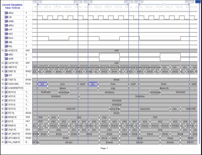
LDA_imm16_PHA16_PHW_imm16..JPG [ 259.49 KiB | Viewed 2246 times ]

The following trace shows the operation of the core for the LDA (zp) and INC zp instructions when preceded by the SIZ and ISZ prefix instructions, respectively. Notice that the operation of the INC zp instruction has been increased from 8 bits to 16 bits, and that its zp direct addressing mode has been converted to zp indirect addressing mode.
Attachment:
LDA16_(zp)_INC16_(zp).JPG
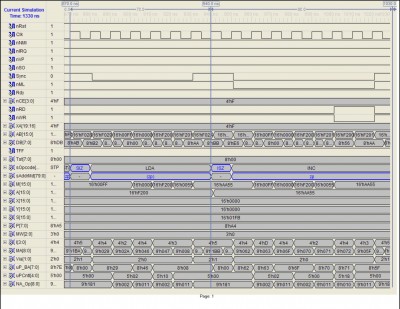
LDA16_(zp)_INC16_(zp).JPG [ 254.39 KiB | Viewed 2246 times ]

The following trace demonstrates how the SIZ prefix applies to the LDX #imm and TXS instructions. Notice that the system stack page has been relocated to page $F200. It will remain located in this page until it is reloaded with an 8-bit TXS instruction, at which time the upper half will be loaded automatically with $01.
Attachment:
LDX_imm16_TXS16_PHW_imm16_Page_1.jpg
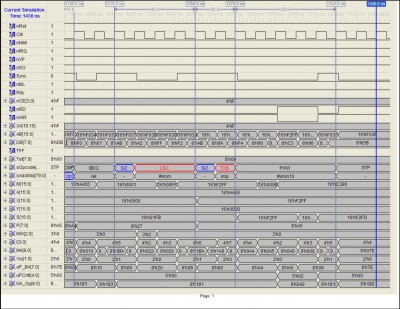
LDX_imm16_TXS16_PHW_imm16_Page_1.jpg [ 255.06 KiB | Viewed 2246 times ]


Edit: replaced $ with # in "LDX $imm", replaced "0x-1" with "0x01", changed "the address generator and the ALU" to "the address generator and the MMU"

_________________
Michael A.


Top
 Profile  
Reply with quote  
PostPosted: Mon Dec 29, 2014 3:26 pm 
Offline

Joined: Mon Mar 02, 2009 7:27 pm
Posts: 3258
Location: NC, USA
MichaelM wrote:
Happy Holidays everyone. I have certainly enjoyed the past few days, and I certainly hope all of you have also.

Yesterday was my 28th wedding anniversary. Had a reservation at a nice local restaurant, and expected nothing but an uneventful, quite dinner of good food with my wife and youngest child. However, my wife had a little incident with with a little bread roll that certainly leads to the observation that restaurant booths may be more cozy and private, but they certainly are not meant for applying the Heimlich Maneuver while seated next to someone chocking. One of the waiters jumped in when I slid out of the seat to try and get arms around my wife, and applied the maneuver. All ended well, and she even had some desert after calming down a bit. Certainly was more excitement than either us planned on having....

Congrats, you're beating the odds being together for so many years. Sorry to hear about the choking incident, but at least it didn't ruin your night!

_________________
65Org16:https://github.com/ElEctric-EyE/verilog-6502


Top
 Profile  
Reply with quote  
PostPosted: Wed Dec 31, 2014 6:46 pm 
Offline
User avatar

Joined: Fri Dec 11, 2009 3:50 pm
Posts: 3346
Location: Ontario, Canada
MichaelM wrote:
it would be advantageous to support IP-relative unconditional and conditional branch instructions and an IP-relative load instruction
AFAIK, there is no benefit to the FIG tradition of expressing branch destinations as an offset from IP. IOW, an absolute address would serve just as well (besides being faster). So, you may wish to limit the effort and resources devoted to supporting IP-relative operations, depending on whether you consider your prospective user base to include a high proportion of FIG adherents. Also, FIG adherents will find your machine attractive regardless, since you've accelerated NEXT (which is by far the largest bottleneck). Supporting IP-relative operations, while a good thought, may be beyond the point of diminishing returns, optimization-wise.

-- Jeff
P.S. -- Happy anniversary, Michael! :)

_________________
In 1988 my 65C02 got six new registers and 44 new full-speed instructions!
https://laughtonelectronics.com/Arcana/ ... mmary.html


Top
 Profile  
Reply with quote  
PostPosted: Wed Dec 31, 2014 11:28 pm 
Offline
User avatar

Joined: Sun Jun 30, 2013 10:26 pm
Posts: 1925
Location: Sacramento, CA, USA
I thought about the same relative vs. absolute branching in my 65m32 ITC Forth, and decided to keep it relative (like its MSP430 Camel code donor roots). On the 65m32, it costs nothing, since IP is already in register y, and ady 0,y+ doesn't take any more space-time than ldy 0,y. The link addresses and CFAs are all absolute, so it doesn't bode well for easy relocation without a re-link or MMU assist, but relative seemed harmless in my case, so I kept it.

YMMV

Mike


Top
 Profile  
Reply with quote  
Display posts from previous:  Sort by  
Post new topic Reply to topic  [ 41 posts ]  Go to page Previous  1, 2, 3  Next

All times are UTC


Who is online

Users browsing this forum: No registered users and 2 guests


You cannot post new topics in this forum
You cannot reply to topics in this forum
You cannot edit your posts in this forum
You cannot delete your posts in this forum
You cannot post attachments in this forum

Search for:
Jump to: