6502.org
http://forum.6502.org/

Design of Parallel Video Board 'Backplane'
http://forum.6502.org/viewtopic.php?f=10&t=2253
Page 1 of 4

Author:  ElEctric_EyE [ Tue Aug 14, 2012 5:50 pm ]
Post subject:  Design of Parallel Video Board 'Backplane'

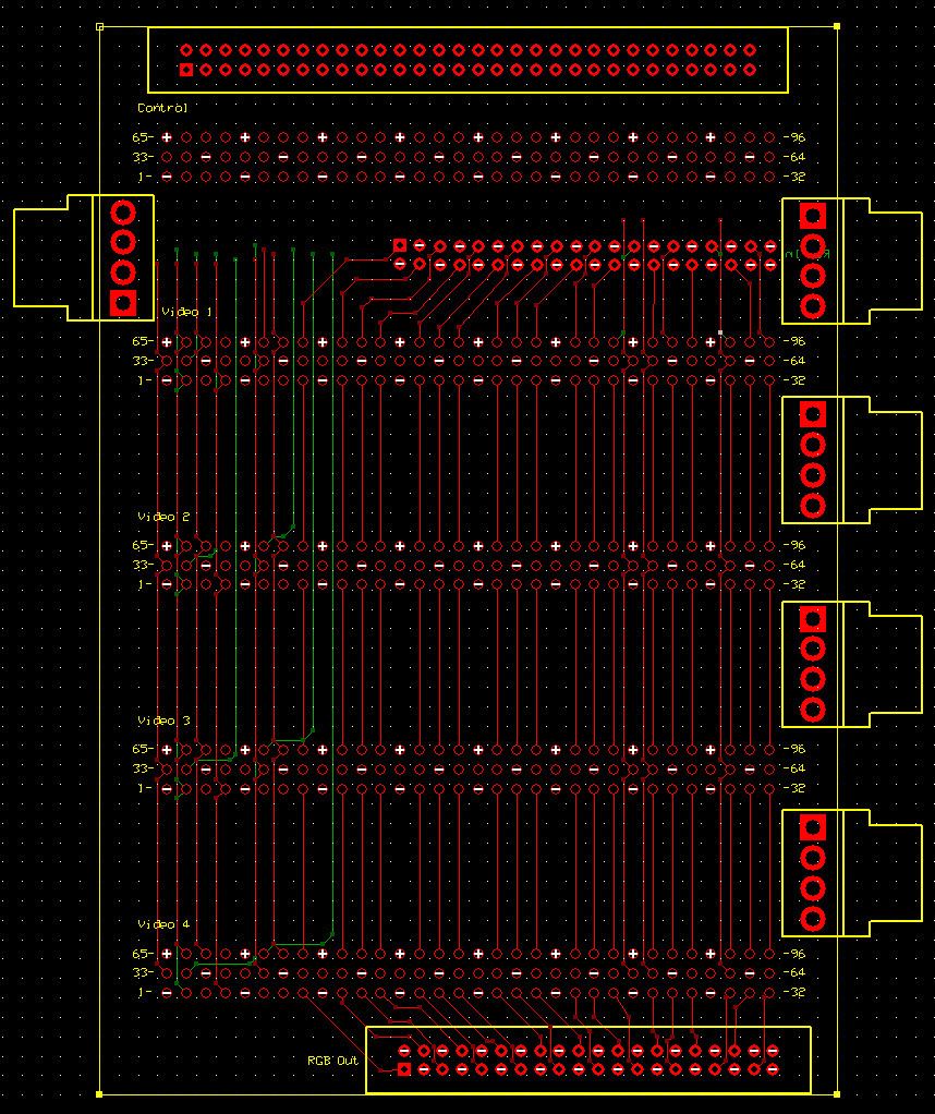
This thread goes hand in hand with the Concept and Design of Parallel 16-bit Video Boards, 16-bits being the RGB video output. There we discuss how we plan to manufacture 1 of these boards. This thread discusses how a multiple of these boards will be connected again using the ExpressPCB service. Although instead of a 3.8"x2.5" 4-layer Miniboard Pro board, this Mainboard will be constructed using their Standard 2-layer service, using a board size of 3.8"x5.5".

6 Parallel Video Boards and a still yet to be designed Controller board will be able to fit on the main connectors K1-K7. Thankfully, the Standard service does not appear to have a hole limitation as this design uses 800+ holes.

After wrestling abit for the layout of this Mainboard, I came to the conclusion this layout must absolutely dictate the assignment of pins for the main connector of the Parallel Video Board. Meaning, at certain points, 2 board layouts (PVB & Mainboard) had to be developed simultaneously.
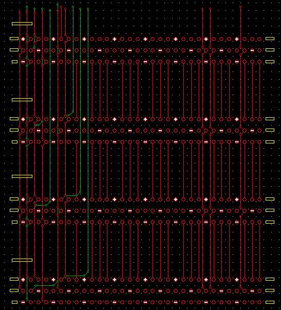
A nice thing I had noticed is that a total of 48-signals can be joined directly using straight traces! This was very good news as early on, as I had not routed a single signal on the bottom layer or have had to use via's...

Also I must mention Garth Wilson, who has contributed significantly to the final layout of this design, spotting some critical errors and making suggestions about improvements for successful high-speed (100+MHz) signal transmission. A great many thanks Garth!

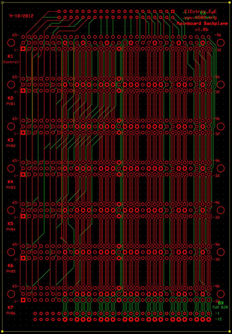
Here is the layout showing 6 PVB headers K2 thru K7. K1 is the controller board. K8 is an expansion header primarily meant for a future HDMI board. K9 is the expansion header meant for a sound board at this point. It uses a 16-bit databus, utilizing the lower 8 bit databus common to all the PVBs. K9's layout is done, but actual pin assignments are still a work in progress. All headers are mounted on top, except for K8 & K9.
Image
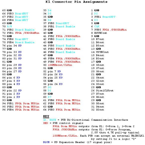
Pin assignments for the K1 Controller Board connector:
Image
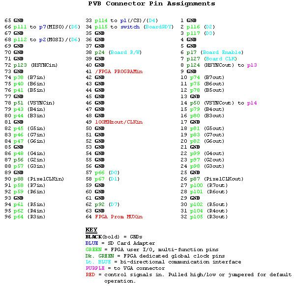
Pin assignments for K2-K7 Parallel Video Boards:
Image
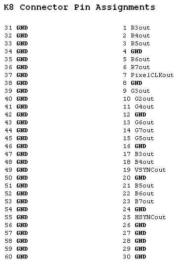
Pin assignments for the HDMI header:
Image
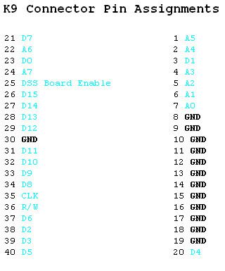
Pin assignments for the Expansion header (in-flux):
Image
Parts list:
Code:
QTY Price     Description               Part#                       Package             Supplier         ID
-------------------------------------------------------------------------------------------------------------
 7 $4.85     96-pin male receptacle    A32857-ND                   vertical thru-hole  Digi-Key    K1,K2,K3,K4,K5,K6,K7
 1 $3.78     40-pin male header        MHB40K-ND                   vertical thru-hole  Digi-Key          K9
 1 $5.63     60-pin male header        MHB60K-ND                   vertical thru-hole  Digi-Key          K8
14 $0.43     M2.5x1" fem/fem spacer    AE10862-ND                  thru hole           Digi-Key
14 TBD       M2.5x15mm Screw           TBA

EDIT: 10/11/12 - Updated and pre-finalized.
EDIT: 10/12/12 - Added K7, K8 pin assignments and parts list.
EDIT: 10/17/12 - Expanded design to include 6 PVB's using same board size.
EDIT: 10/18/12 - This thread is currently a W.I.P.
EDIT: 10/19/12 - Last thread EDIT was a mistake, however updated K1 connector pin assignments
EDIT: 10/23/12 - 2 x Updated parts list
EDIT: 10/23/12 - Updated K8,K9 pics
EDIT: 10/30/12 - Pre-Finalized design
EDIT: 8/05/13 - Changed Title

Author:  ElEctric_EyE [ Sat Aug 18, 2012 2:43 pm ]
Post subject:  Re: Design of Mainboard for Parallel Video Boards

Very easy to route the 18 I/O signals to the controller connector on top (not shown). The signals are 8 I/O Data, R/W, CLK, 4 Board Selects, and 4 Board Ready. I will have room for an expansion connector after all!
Image

Author:  GARTHWILSON [ Sat Aug 18, 2012 6:06 pm ]
Post subject:  Re: Design of Mainboard for Parallel Video Boards

What kind of connectors are these? At first glance I was assuming the 96-pin DIN connectors; but those have .100" row spacing, not .200".

Author:  ElEctric_EyE [ Sat Aug 18, 2012 7:45 pm ]
Post subject:  Re: Design of Mainboard for Parallel Video Boards

The one I'm using on each Video Board and controller board is a right angle female type A32863-ND from DigiKey. The male receptacles used on this mainboard are vertical type A32857-ND.

Author:  GARTHWILSON [ Sat Aug 18, 2012 7:56 pm ]
Post subject:  Re: Design of Mainboard for Parallel Video Boards

Yes, DIN 41612 connectors have the rows .100" apart, not .200". You can see it if you click on "datasheet" on the pages you linked. I have a bunch of those I got in WW for a project I never went through with.

Author:  ElEctric_EyE [ Sat Aug 18, 2012 11:42 pm ]
Post subject:  Re: Design of Mainboard for Parallel Video Boards

GARTHWILSON wrote:
...I was assuming the 96-pin DIN connectors; but those have .100" row spacing...

You assumed correct then. I can't afford .2" pin spacing on a 3.8" wide board with a 96-pin 3-row connector..
GARTHWILSON wrote:
Yes, DIN 41612 connectors have the rows .100" apart, not .200"...

If I had a spec sheet full of connector types, I would shave searched for this DIN 41612, would've save me quite a few hours.

Author:  ElEctric_EyE [ Fri Aug 24, 2012 8:04 pm ]
Post subject:  Re: Design of Mainboard 'Backplane' for Parallel Video Board

Update: I was able to add some expansion connectors. One 60-pin connector (on top) will be for signals coming off the Control board to future boards. I also added 2 40-pin expansion connectors for RGB-in and RGB out signals so more boards can be cascaded. The RGB in connector will have to be mounted on the bottom, all others on top. Lastly adding in the separate power connectors did not max out my pincount, which is @646. 6 mounting holes are not shown yet.
Image

Author:  GARTHWILSON [ Fri Aug 24, 2012 8:32 pm ]
Post subject:  Re: Design of Mainboard 'Backplane' for Parallel Video Board

Is the change to .100" row spacing on the connectors still coming? I don't know of a single connector on the market that will fit the .200" row spacing shown on your board.

Author:  ElEctric_EyE [ Fri Aug 24, 2012 8:44 pm ]
Post subject:  Re: Design of Mainboard 'Backplane' for Parallel Video Board

Ah, I had a feeling we weren't on the same page Garth. .1" spacing has always been shown on this thread for all the connectors. So those 96 pin connectors are fitting nicely in the 3.8" wide x 5.5" long mainboard.

Author:  GARTHWILSON [ Fri Aug 24, 2012 9:08 pm ]
Post subject:  Re: Design of Mainboard 'Backplane' for Parallel Video Board

Correction-- you have them on .150" row spacing, not .200", according to the grid of gray dots which are no doubt on .100" centers. So at the left end, you have .150" spacing between pin 1 and pin 33, and between pin 33 and pin 65. You do have .100" between pins 1 and 2, but not between the rows.

Author:  ElEctric_EyE [ Fri Aug 24, 2012 9:23 pm ]
Post subject:  Re: Design of Mainboard 'Backplane' for Parallel Video Board

You're correct Garth! A huge error on my part which was multiplied by the copy/pasting. Thank goodness I was more careful on the PVB. I should've made a custom part and saved it to the library, but am always in a rush. Thanks for spotting that, I'll make the corrections.

EDIT: Made the correction to last pic.

Author:  ElEctric_EyE [ Wed Sep 12, 2012 12:09 pm ]
Post subject:  Re: Design of NEW 65Orgxx Devboard 'Backplane'

Some updates on this board design:

1) No power is distributed through it. Current plans are for all powers to go straight to each board now. New pic will be added & updated on header post today.
2) The controller board will have IDE support using this IC with it's own 80-pin connector. So the expansion connector can now be generally devoted to an audio solution.

Author:  ElEctric_EyE [ Thu Oct 11, 2012 9:13 pm ]
Post subject:  Re: Design of NEW 65Orgxx Devboard 'Backplane'

Pre-finalized the Mainboard today. Updated the head post.

EDIT: I should most certainly mention Arlet has volunteered to populate a bare PVB v1.0h board with his own time and funds, although he has stated he is not interested in the primary feature of the v1.0h board, which is it's ability to address 4MB of video memory using a 5.5ns SyncRAM. This version does address a design error, another error, and an addition and so should be easier to assemble... This action on Arlet's part is most certainly appreciated and it's why I'm able to get these Backplane Mainboard's manufactured here in 1/2 half the earlier anticipated time (2 weeks). These larger boards are $195 for 4 of them. I will be keeping 3...

Re-EDIT: I've checked spacing on the PVB connectors on this board, now that a real PVB exists with all connectors soldered. There is a gap of .1" when these 4 PVB's are eventually vertically stacked side by side using the current dimensions. This worst case is if the tallest part of the VGA connector were actually within a board boundary which it isn't, but not enough space to take advantage of either.

Author:  ElEctric_EyE [ Tue Oct 16, 2012 1:23 pm ]
Post subject:  Re: Design of NEW 65Orgxx Devboard 'Backplane'

I just had the realization of using another one of ExpressPCB services to bring down the costs so that I may be able to purchase this board in a few days.

Using their Standard service, I can get 2 boards made for ~$100. The size limitation is gone also and the temptation was their to increase the number of PVB slots from 4 to 8, thereby maximizing pin usage from the control board connector. This increase in board size would be negligible in cost, however with the realization that in the past I have missed errors or have had other small oversights with all of my first attempts so far I will go ahead with the current design and hopefully put this order in 2 days. Definately, by next week though.

Author:  ElEctric_EyE [ Tue Oct 16, 2012 3:36 pm ]
Post subject:  Re: Design of NEW 65Orgxx Devboard 'Backplane'

Using the current layout of 3.8"x5.5", and after taking physical measurements of a real PVB, I am able to push the PVB's closer together on the layout and fit 6 of them within the current real estate. This will be the last change. One more week. I'll update all the info on the header as I catch up to the modifications.

EDIT: I will update the head pic. I see an error on K6 where the main clock shield ground (underneath) is touching a signal.

Page 1 of 4 All times are UTC
Powered by phpBB® Forum Software © phpBB Group
http://www.phpbb.com/