6502.org
http://forum.6502.org/

Concept & Design of 3.3V Parallel 16-bit VGA Boards
http://forum.6502.org/viewtopic.php?f=10&t=2247
Page 4 of 41

Author:  ElEctric_EyE [ Tue Sep 18, 2012 1:09 pm ]
Post subject:  Re: Concept & Design of Parallel 16-bit VGA Boards

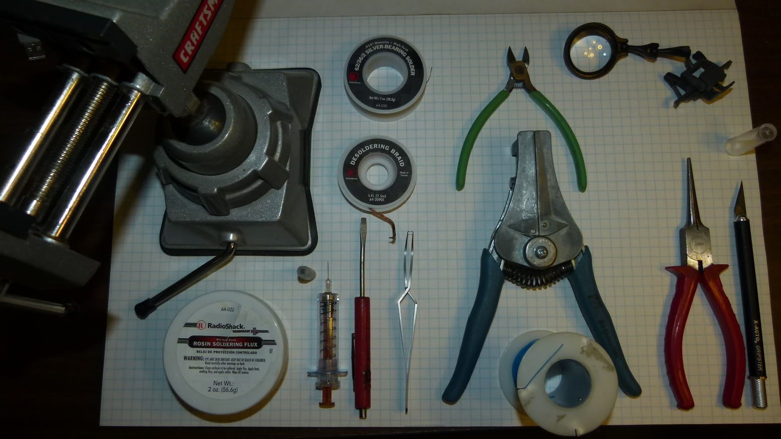
Tools I use: Multi-Axis Vice (for holding board in place), .015" silver bearing solder, fine tip wire cutter(for corrections), clip on magnifier, desoldering braid(suggested by others, but not used here), wirewrap insulation strip tool (for corrections), fine tip long needle nose pliers (for placing corrections), X-Acto knife (for corrections), flux, needle containing flux, flat tip screwdriver (IC final placement & holdown), tweezers (for general small part placement),
Image

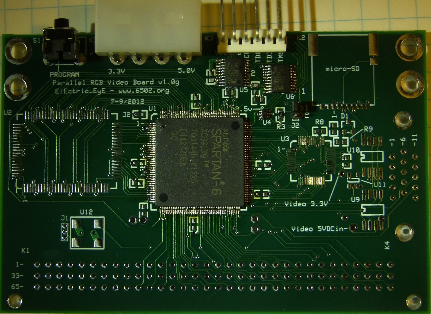
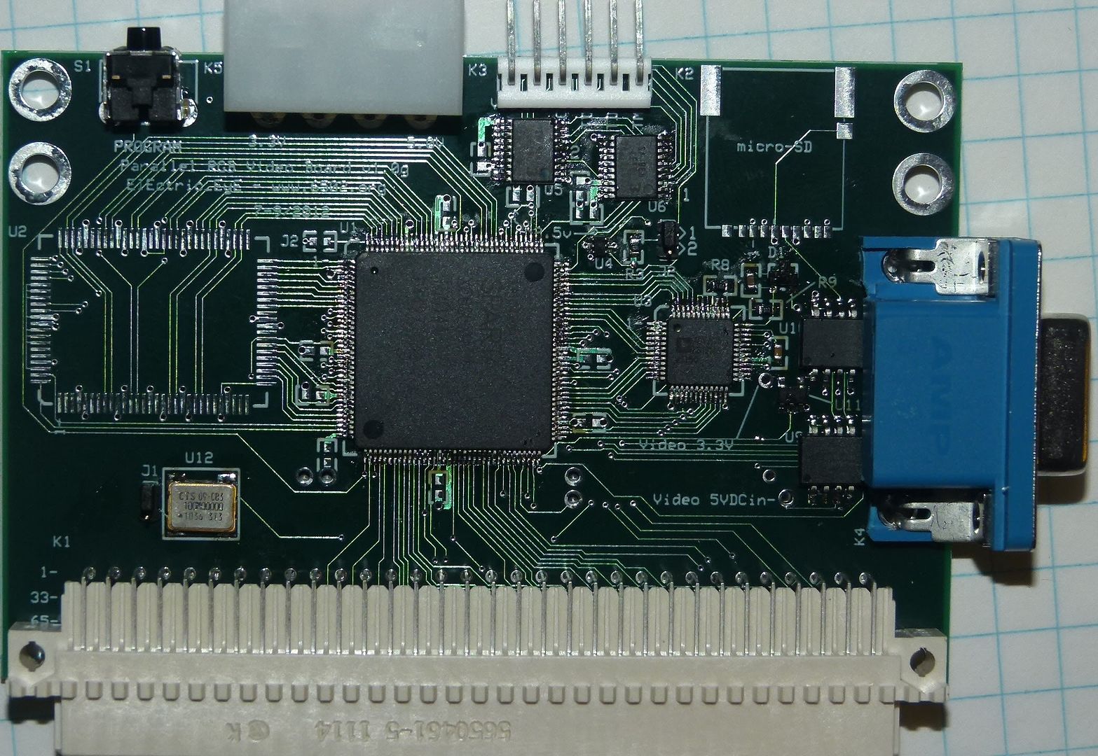
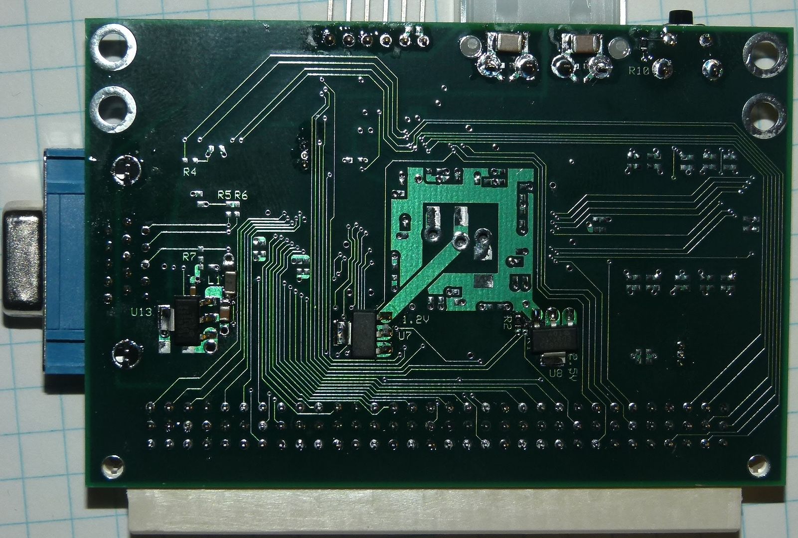
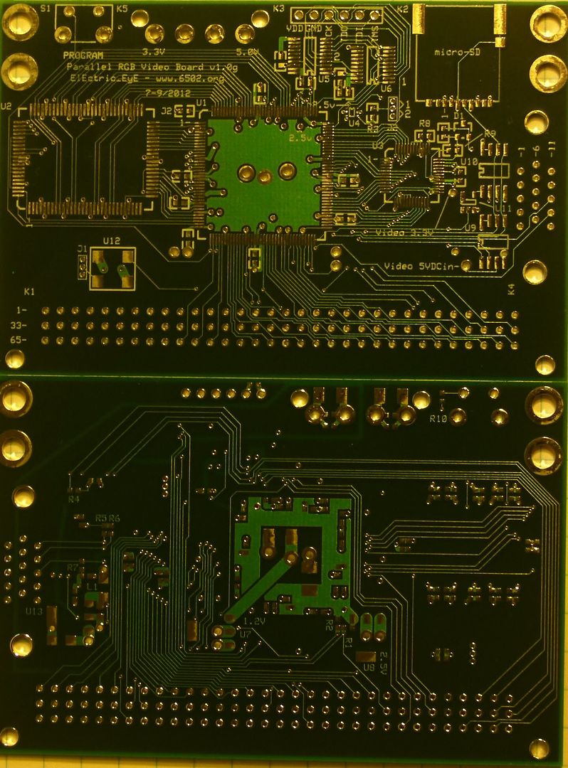
Bare boards. Start time is 9am. I will solder in the Spartan 6, power connector, JTAG connector and associated resistors, FPGA Proms, the MUX for FPGA program stream w/pull-up resistor and jumper, and finally 1.2V/2.5V VRegulators for FPGA.
Image

EDIT (9/19/2012): 1st pic updated. Description updated.

Author:  ElEctric_EyE [ Tue Sep 18, 2012 2:57 pm ]
Post subject:  Re: Concept & Design of Parallel 16-bit VGA Boards

Took a little more than 1hr... U4 and the 0603 SMT resistors were the most challenging, the pads must be made larger for U4 in v1.0h. The Spartan 6 was actually the easiest to do. I'm going to go without soldering in the bypass capacitors for as long as possible. Now it's time to rewire a female power adapter for 3.3V & 5V to match the above male connector. Then I power it up and hopefully ISE will see the 2 PROMs and the S6 :!:
Image

Author:  ElEctric_EyE [ Tue Sep 18, 2012 3:19 pm ]
Post subject:  Re: Concept & Design of Parallel 16-bit VGA Boards

Initial testing looks promising!!! ISE sees both PROMs and the S6. I was able to separately program each PROM and the S6 itself (using a project from the past), and ISE was able to verify the programming of each. So this is very good news.

Now I will solder in the videoDAC and it's associated parts and the VGA connector.

For initial testing of the video signal without using the RAM, I would like to use and modify some HDL code shared from www.FPGA4FUN.com using the pong game example. Maybe make a simple change and program the PROMs for 2 different resolutions.

Author:  BigDumbDinosaur [ Tue Sep 18, 2012 4:02 pm ]
Post subject:  Re: Concept & Design of Parallel 16-bit VGA Boards

ElEctric_EyE wrote:
Tools I use: Vice for holding board in place, .015" solder, clip on magnifier, flux, finest tip soldering pencil, tweezers for general placement, flat tip screwdriver for final placement and hold down, needle containing flux.

Something I don't see in your "arsenal" is solder wick (aka braid). You can use it to clean up the soldering on the Spartan 6 and give it that factory look. I use it to clean up after soldering fine pitch stuff so as to guarantee that no microscopic bridges exist.

Author:  Arlet [ Tue Sep 18, 2012 5:02 pm ]
Post subject:  Re: Concept & Design of Parallel 16-bit VGA Boards

I use Multicore Crystal 511 solder wire. It has mildly activated flux, and has good wetting capabilities. I like it better than standard rosin flux. I agree with BDD about the braid.

A useful trick is to place the part, apply some flux to the pins, and take a piece of solder braid and fill the tip with solder. Then put the braid on the PCB, and use the iron to push it against the tips of the pins. When done correctly, a small amount of solder will wick from the braid to the pin/pad, and make a nice clean joint. It's really easy and quick.

Author:  ElEctric_EyE [ Tue Sep 18, 2012 6:01 pm ]
Post subject:  Re: Concept & Design of Parallel 16-bit VGA Boards

Gentlemen, thanks for the tips!

I am done construction for today. As I mentioned before, there was a space conflict in this design involving the serial FLASH ICs and the VGA connector. I had to solder in the FLASHs first and grind some material off the bottom part of the VGA connector, or I wouldn't have been able to mount them after the VGA connector was mounted... Anyway, all seems good so far. It still powers up and no behavior has changed for the worse.

I must give my frayed nerves a rest. I was actually shaking pretty bad during assembly :lol:, but I managed. Breathing is key.

I used the camera flash for these pics. The pictures are abit deceiving as it appears some of the remaining flux is reflective and appears to look like solder.
Image
Image

I think it is time to start an implementation thread. I have a few errands to do before I do this...

Author:  ElEctric_EyE [ Wed Sep 19, 2012 12:24 pm ]
Post subject:  Re: Concept & Design of Parallel 16-bit VGA Boards

Today I was trying to generate HSYNC and VSYNC signals, but no activity from the FPGA. I saw activity coming from both PROMs when the Program button was pushed, but no activity out of the MUX (U4). Then I realized I have the output (pin4) and select (pin6) lines switched. When I disconnected the jumper which pulls the output (should be select) high or low thru a 4.7K resistor, I still see no activity which sort of bothers me. I can fix this mistake relatively easily, although I think I will purchase an X-Acto knife today before I do this.

Author:  ElEctric_EyE [ Wed Sep 19, 2012 3:58 pm ]
Post subject:  Re: Concept & Design of Parallel 16-bit VGA Boards

Got the knife, made the corrections and I see signs of life! The VGA monitor light turns green recognizing the HSYNC and VSYNC signals, and the 25MHz pixelclock is coming out of the FPGA.

Version 1.0h is up to date. I was actually making other modifications to the layout as I was assembling this board. Time for some code on the Implementation thread.

EDIT: I will update the tools pic at the top of this page. I don't wish to intimidate, but also people make mistakes, and there are tools I used to correct mistakes, plus that original pic is pretty bad...

Author:  ElEctric_EyE [ Wed Sep 26, 2012 1:06 pm ]
Post subject:  Re: Concept & Design of Parallel 16-bit VGA Boards

So I was getting some kind of picture in my testing using a simple ramp pattern generator. It was not 100%. Testing Red and Blue seemed ok, but Green was not ramping correctly. And after finding an error in pin assignments in the .ucf file early on, Green is still not ramping correcty. Then I realized this morning when I was touching some pins especially near the videoDAC, I would lose the picture entirely. So I added in the 75 ohm load resistors on the videoDAC outputs. Now nothing at all, except the H/VSync's and pixel clock. That's when I realized yet another design flaw. The complimentary RGB outputs are not grounded as the datasheet specifies. Time for some soldering...

My Tektronix 2440 'Scope is starting to go on the fritz too. :cry: Screen freezing up intermittently. This version I can send out to be fixed. But we'll see how much longer I can squeeze usefulness out of it.

EDIT:Got it working! Besides grounding the complementary outputs, I touched up the solder around the videoDAC. Something was very finicky there, this being the 3rd touchup, but now it finally works.

Author:  BigDumbDinosaur [ Wed Sep 26, 2012 4:41 pm ]
Post subject:  Re: Concept & Design of Parallel 16-bit VGA Boards

ElEctric_EyE wrote:
Tools I use: Multi-Axis Vice (for holding board in place)...

I was going to ask: how do you get the vise (I assume you meant "vise", not "vice" :lol:) to stay affixed to the bench? I have one just like it and it will not stay put for more than about a minute—it doesn't hold vacuum for very long.

Author:  BigEd [ Wed Sep 26, 2012 5:06 pm ]
Post subject:  OT: dialects of English

Hey, on this side of the pond it's a vice! (But EEye is on your side of the pond...)

Author:  BigDumbDinosaur [ Wed Sep 26, 2012 8:06 pm ]
Post subject:  Re: OT: dialects of English

BigEd wrote:
Hey, on this side of the pond it's a vice! (But EEye is on your side of the pond...)

If I see "vice" in print I usually think bad things, e.g., excessive drinking. :lol:

Author:  ElEctric_EyE [ Wed Sep 26, 2012 11:45 pm ]
Post subject:  Re: Concept & Design of Parallel 16-bit VGA Boards

BigDumbDinosaur wrote:
I was going to ask: how do you get the vise (I assume you meant "vise", not "vice" :lol:) to stay affixed to the bench? I have one just like it and it will not stay put for more than about a minute—it doesn't hold vacuum for very long.[/size]

My "vise" sticks for about 2 minutes. It is a vacuum based vice, probably same as yours, placed on a veneer type table, so it isn't mounted on an absolutely flat suction leak-free surface. But it's good enough for me. As Tradesmen, we learn our tools...

Author:  ElEctric_EyE [ Thu Oct 04, 2012 8:19 pm ]
Post subject:  Re: Concept & Design of Parallel 16-bit VGA Boards

While looking for cheaper prices from Cypress competitors, I actually came across a faster SyncRAM made by a company called GSI technology. And it's $15 cheaper @$139US and has an access time of 5.5ns, 1 ns faster. Looking into a 4Mx18 version. Avnet suggested this part as a replacement when I was searching for the Cypress 4Mx18 part.

Digikey does not seem to stock GSI parts.

EDIT: 5.5ns =181.8MHz. 1900x1080x60Hz = 180MHz according to this site. 1900x1080=2.052M pixels, almost exactly half(2.097M) of a 4Mx18 SyncRAM.

Author:  Arlet [ Thu Oct 04, 2012 9:46 pm ]
Post subject:  Re: Concept & Design of Parallel 16-bit VGA Boards

ElEctric_EyE wrote:
While looking for cheaper prices from Cypress competitors, I actually came across a faster SyncRAM made by a company called GSI technology. And it's $15 cheaper @$139US and has an access time of 5.5ns, 1 ns faster. Looking into a 4Mx18 version. Avnet suggested this part as a replacement when I was searching for the Cypress 4Mx18 part.

Digikey does not seem to stock GSI parts.

EDIT: 5.5ns =181.8MHz. 1900x1080x60Hz = 180MHz according to this site. 1900x1080=2.052M pixels, almost exactly half(2.097M) of a 4Mx18 SyncRAM.


More important than the access time is the max clock frequency, both of the SRAM, and what you can manage to get done with the FPGA and on the board. At these frequencies, it will be challenging. In any case, there's more than just the access time of the SRAM. There's also the output delay of the FPGA pad, the trace delays on the PCB, and the input delay on the FPGA. All together probably good for another 4-5 ns of delay.

Page 4 of 41 All times are UTC
Powered by phpBB® Forum Software © phpBB Group
http://www.phpbb.com/