6502.org Forum  Projects  Code  Documents  Tools  Forum
It is currently Thu Sep 19, 2024 10:13 pm

All times are UTC


Post new topic Reply to topic  [ 8 posts ] 
Author Message
PostPosted: Wed Feb 06, 2019 3:00 pm 
Offline
User avatar

Joined: Wed Aug 17, 2005 12:07 am
Posts: 1228
Location: Soddy-Daisy, TN USA
I've seen various techniques for driving seven segment displays. Without using PLD's or IC's with tons of pins, was it common for early manufacturers to multiplex the active segment rapidly? I've seen, for example, old alarm clocks on TV and you can see the flickering because the refresh rates were different.

I want to drive 6 or so segments myself with a single VIA. I'm thinking of using one port for the EEPROM address (using ROMS to drive each segment) and another port to rapidly cycle through chip enables.

In fact, might even use a counter or something and have one pin drive all segments.

Is this logic sound or is there something I'm missing?

Thanks


**EDIT**

I realize, that experimenting is 90% of the fun...I will test this out myself but it's a good 10 hours until I can get to my bench and I'm impatient.

LOL

_________________
Cat; the other white meat.


Top
 Profile  
Reply with quote  
PostPosted: Wed Feb 06, 2019 3:28 pm 
Offline

Joined: Thu Mar 03, 2011 5:56 pm
Posts: 284
I believe it was common to multiplex digits, so that all segments that should be on for a single digit would be active at the same time. Note that this requires a mechanism to select a single digit at a time.

Back in 1983 or so I wrote code that combined display multiplexing with keypad scanning (including key debounce); this would be a good way of reducing the overhead if you have both a multiplexed display and a key matrix to scan.


Top
 Profile  
Reply with quote  
PostPosted: Wed Feb 06, 2019 3:30 pm 
Offline

Joined: Mon Mar 05, 2018 6:31 pm
Posts: 8
Multi-digit displays would cycle through the digits, displaying one at a time, quickly. A single digit only has 8 LED's, so on an 8 bit bus it's not saving you anything. You could use a latch to set the segment values.

If you meant you wanted to drive 6 digits, not 6 segments, then yes you can multiplex in software. It might be kind of flickery and dim if you drive them a single segment at a time, each segment only gets 1/48th of however you slice up time to light up.


Top
 Profile  
Reply with quote  
PostPosted: Wed Feb 06, 2019 3:51 pm 
Offline
User avatar

Joined: Wed Aug 17, 2005 12:07 am
Posts: 1228
Location: Soddy-Daisy, TN USA
Those are good points.

Maybe I'm getting my terminology wrong. When I say "digit", I'm referring to the entire LED of 7 segments (or 8 if you count DP). And, I would have a single EEPROM that has it's data bus connected to all 7 (or 8 ) segments of the single digit.


Also, another good point on the brightness. I want four digits for the address display and two for the data. So yeah, each digit would only be on for a relatively short amount of time.

The latch idea is a good one!

So, the EEPROM would feed the latch which in turn would feed the LED. I imagine I would need to drive the latch pins too but maybe a counter could do that.

Thanks!

_________________
Cat; the other white meat.


Top
 Profile  
Reply with quote  
PostPosted: Wed Feb 06, 2019 4:43 pm 
Offline
User avatar

Joined: Thu Dec 11, 2008 1:28 pm
Posts: 10938
Location: England
Here are two most excellent web pages to consult, by Ken Shirriff:
https://righto.com/ti
https://righto.com/sinclair
These two calculators are built on essentially the same single chip from TI, recustomised according to two different programs. In the first of those pages, you can see that the constantly circulating one-cold signals in the D register are used to drive each of the 9 digits in turn, and at the same time allowing the two input lines to sense any keypress on the 18-key keypad. The digit-by-digit operation of the calculator is bound fairly tightly to this scanning, I think, although it must surely proceed LSB to MSB in the ALU.

It turns out that diode properties and human visual perception are such that intermittent illumination is a great deal more energy-efficient than constant illumination. So, battery-powered LED calculators were only practical when the display is scanned in this kind of way. I've a feeling the LEDs are even overdriven according to their rating at constant illumination, which was essential to get a sufficiently bright display. I think HP have a piece on the design of the HP-35 which might go into that... hmm, maybe it's in there somewhere:

Quote:
It was apparent early in the HP-35 planning that new display techniques would be required. Existing light-emitting-diode products used too much power and cost too much. HP Associates developed a magnified five-digit cluster which saves both power and cost and is packaged in a convenient 14-pin pack age (Fig. 5). Each digit has a spherical lens molded in the plastic over it. A slight reduction in viewing angle results, but for the handheld calculator this is not a problem.

LED's are more efficient if they are pulsed at a low duty cycle rather than driven by a dc source. In the HP-35, energy is stored in inductors and dumped into the light-emitting diodes. This drive technique allows a high degree of multiplexing; the digits are scanned one at a time, one segment at a time.

Customized bipolar anode and cathode driver circuits incorporating the required features were developed and are manufactured by HP. The anode driver generates the two-phase system clock and the segment (anode) drive signals, decodes the data from the arithmetic and register chip and inserts the decimal point, sends shift signals to the other axis of the multiplex circuitry (the cathode driver), and senses low battery voltage to turn on all decimal points as a warning that about 15 minutes of operating time remains. The cathode driver contains a 15-position shift register which is incremented for each digit position.


Top
 Profile  
Reply with quote  
PostPosted: Wed Feb 06, 2019 5:22 pm 
Offline
User avatar

Joined: Wed Feb 14, 2018 2:33 pm
Posts: 1466
Location: Scotland
Yes, it was common. You have the trade-off between writing a bit more code or using more hardware IO pins.

You can get away with as little as one resistor per digit and nothing else - see e.g. 
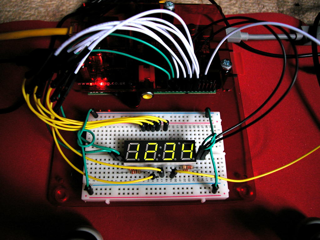
https://projects.drogon.net/wp-content/ ... 7/led2.jpg This is on a Raspberry Pi, but the principle is the same. In this scenario I'm only lighting up one segment at a time so I have to rely on the software loop to scan fast enough to get them bright enough for persistence of vision to work without flicker.

(Note that the Pi can sink the same amount of current as it can source - not all IO chips or microcontrollers can, so this might not apply)

This article shows using one resistor per segment and a transistor to drive each digit (actually a uln2803, but the same idea) https://projects.drogon.net/raspberry-p ... t-drivers/ (see note below)

I prefer that way as it's lighting up one digit at a time rather than one segment which can reduce the flicker and make the software easier but it needs more hardware.

So 6 digits (which I presume you mean), I'd do it as follows: Use one 8-bit port for the segments. Put 8 resistors on the 8 outputs and connect to the segments which you've all wired in parallel - ie. segment A on digit 1 to segment A to digit 2 and so on. (Make sure the port can source enough current when all 8 are on!)

The common pin for each digit wired to a suitable transistor (or darlington) (and this will depend on you using common anode or common cathode digits). You may need a resistor to the base of the transistor, pick one to make sure the transistor is fully saturated when you turn it on. These 6 outputs go to 6 pins on the other VIA port.

Then:

Foreach digit
output the segments to make the actual number on the 8-bit port (use a 16-byte lookup table in ROM to map a 4-biy hex number to an 8-bit segment pattern)
enable common pin on that digit
delay (maybe just a millisecond or so)
disable common pin
repeat

If you had a regular interrupt routine then it could do one step of that loop every interrupt, picking up the data from 6 memory locations, then all you need do is update the memory locations from any code and it will "magically" appear on the display.

Simples ;-)

You can optimise the VIA ports by using external hardware, but you're then in the world of trading off software for more hardware and so on and only you'll know what's best - e.g. your counter idea. Use a single pin on the VIA (say one of the control lines) to clock the counter going to the transistor to enable each digit in turn. You either need to know the initial state, or have another line to act as reset for the counter. If I really had to optimise the VIA pins, then 3 pins would get me into 2 74x595 shift registers which would be enough to drive up to 8 digits - the software outputting a 16-bit value each cycle - 8 bits into the segments and 8 into the digit drivers. (Maybe even using the shift-register in the VIA to clock the data out)

I think the eeprom idea is nice, but overkill - you're using the eeprom as a 4 to 8 decoder (as I understand it). There are 74 series TTL that do it though - see 7446 through 7479 although that's optimising the bits on the VIA - using only 3 bits rather than 8 to drive each segment.

Cheers,

-Gordon

Note: That display is off an Elektor Junior Computer which I made many years ago then stupidly stupidly stupidly cannibalised for bits for another 6502 project. What a muppet. Every time I see that display I kick myself. Ah well. Hindsight and all that!

_________________
--
Gordon Henderson.
See my Ruby 6502 and 65816 SBC projects here: https://projects.drogon.net/ruby/


Top
 Profile  
Reply with quote  
PostPosted: Wed Feb 06, 2019 5:35 pm 
Offline
User avatar

Joined: Wed Feb 14, 2018 2:33 pm
Posts: 1466
Location: Scotland
On magnified "bubble" type calculator displays:

https://unicorn.drogon.net/stuff/mk14-e.jpg

And you can still buy similar displays today... or you could as Pimoroni in the UK sold new 4-digit ones for a while, but seem to have stopped stocking them. Ah well, back to the ebay scalpers..

-Gordon

_________________
--
Gordon Henderson.
See my Ruby 6502 and 65816 SBC projects here: https://projects.drogon.net/ruby/


Top
 Profile  
Reply with quote  
PostPosted: Wed Feb 06, 2019 5:50 pm 
Offline
User avatar

Joined: Fri Dec 11, 2009 3:50 pm
Posts: 3367
Location: Ontario, Canada
cbmeeks wrote:
I want to drive 6 or so segments myself with a single VIA. I'm thinking of using one port for the EEPROM address (using ROMS to drive each segment) and another port to rapidly cycle through chip enables.
The VIA part makes sense, but you lost me when you mentioned EEPROM. Are you thinking the EEPROM would be a Character Generator wired directly to the segments? Sorry but I don't follow you. It'd be better to implement the Character Generator in software -- that's what is usually done. Then the software writes to a port which drives the segments.

The KIM-1 display is a good example to study, especially since it's quite well documented in the KIM 1 User Manual.

Each digit (collection of 7 segments) remains off until it gets its turn, which is only 1/6th of the time (because there are 6 digits). The digit selection is made by the 74145 decoder at the top of the diagram. Driving up from below are signals for the seven segments, which originate from the peripheral port at the bottom. The port outputs data almost constantly, with that data being updated as each digit gets its turn.

To read the key matrix, the 74145 decoder is commanded to activate each of its four output lines on the left. The peripheral port at the bottom is temporarily switched to input mode, allowing keypress information to be read. For the program listings, see Appendix 1 of the manual.

ETA: nowadays the transistors and the inverters and NAND could be eliminated. They're used here to boost the current of the signals. But a modern decoder and VIA port could drive the display directly.

-- Jeff


Attachments:
KIM-1 LED display.gif
KIM-1 LED display.gif [ 133.74 KiB | Viewed 1205 times ]

_________________
In 1988 my 65C02 got six new registers and 44 new full-speed instructions!
https://laughtonelectronics.com/Arcana/ ... mmary.html
Top
 Profile  
Reply with quote  
Display posts from previous:  Sort by  
Post new topic Reply to topic  [ 8 posts ] 

All times are UTC


Who is online

Users browsing this forum: No registered users and 12 guests


You cannot post new topics in this forum
You cannot reply to topics in this forum
You cannot edit your posts in this forum
You cannot delete your posts in this forum
You cannot post attachments in this forum

Search for:
Jump to: