6502.org Forum  Projects  Code  Documents  Tools  Forum
It is currently Tue Jun 25, 2024 5:37 am

All times are UTC


Post new topic Reply to topic  [ 7 posts ] 
Author Message
PostPosted: Thu Jun 12, 2014 9:36 pm 
Offline
User avatar

Joined: Wed May 30, 2012 7:45 pm
Posts: 58
Location: Dallas, TX
I can't help but be jealous when I see excellent penmanship. For instance, take a look at Garth's work here: http://wilsonminesco.com/6502primer/basic6502schem.jpg

I know that everyone is using Eagle, or some other software to draw up schematics these days. But, I happen to love the oldschool way of drawing
up schematics by hand. I can't help but wonder how these skills are honed. For instance, did any of you get this sort of training in college? Or, do
some of you perhaps use stencils?

I thought it would be an interesting discussion considering that many on this forum like older methods. To me the biggest challenge is layout. I can't
seem to master the spacial requirements of my drafts. Perhaps there's an old trick I could learn here. Google searching didn't yield much I'm afraid,
so I'm hoping you guys might have some nuggets of wisdom.

Thanks,

_________________
http://www.thestarrlab.com


Top
 Profile  
Reply with quote  
PostPosted: Thu Jun 12, 2014 10:11 pm 
Offline

Joined: Sun Apr 10, 2011 8:29 am
Posts: 597
Location: Norway/Japan
I was trained in technical drawing during my electronics education. But I was terrible at it. I'm so bad at it that I can't even use graphical tools. Can't do simple drawings either. I recently did some woodwork where I had to design, construct and build the whole thing. Couldn't find any way of illustrating it, so I had to do it all in my head and keep it there. Took me weeks to finish in my spare time, so it was a bit of work. I did take it slowly though, to get it right without drawings (woodwork is not my normal field).

I'm mainly a programmer these days, so needless to say, I'm happy that the days of "Case" design and tools are over. Designing with bubbles and arrows and GUIs is a total waste of time for me.
My mind is visual though, just not in a way which matches the physical world..
I did produce some PCBs the manual way (with the old-fashioned methods) back in the seventies and early eighties, but I suspect that I used pre-designed layouts except for the most simplistic things. Can't remember. (Edit: Wire-wrap is a different story though - so that's what I used for one-off projects later)
So, these days I rely on other people's PCB designs, I just solder and write code! :)

So, to get back to your question, I guess many people here received training. It was certainly part of the curriculum in my own education. It's just that for a few of us it helped very little! :)

-Tor


Last edited by Tor on Fri Jun 13, 2014 9:08 am, edited 1 time in total.

Top
 Profile  
Reply with quote  
PostPosted: Thu Jun 12, 2014 10:25 pm 
Offline
User avatar

Joined: Fri Aug 30, 2002 1:09 am
Posts: 8460
Location: Southern California
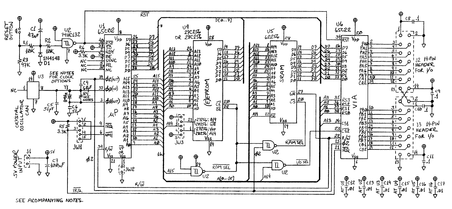
Thankyou for the compliment, Johnny! No training here, but I did use a template for the NAND gates in the drawing you referenced. I used OrCAD at my last place of work and got very, very proficient at it, but was always frustrated that I could not get the layout just the way I wanted it, as you wrote:
Quote:
To me the biggest challenge is layout. I can't seem to master the spacial requirements of my drafts.
In CAD, you form your schematic components in a way that seems logical at the time (or use ones that are already supplied); but then when it comes time to draw a schematic, you find you have to re-arrange pins to get the most logical and clear placement of connecting lines. Since that's not practical, you end up with lots of extra crossings and elbows and tees, reducing the readability, plus empty spaces you can't make good use of.

The CAD I use now for PC-board layout is an old version Easy-PC Pro from Number One Systems in England, but I don't use the schematic portion of it because I don't like the way it works. That means I also don't use the netlists, ratsnesting, etc.. With my system of checks, I do not get PCB layout errors. Schematic capture, working with the PCB layout software, is supposed to eliminate layout connection errors, but we still got them in OrCAD.

In my flat file, I have C-size (18"x24") drawings with about 500 very small schematic component symbols each. The resistor numbers by themselves get over 200. Feature sizes are much too small to copy by blueprint, but today you can get photocopies on bond paper up to something like 48" or 60" wide, and much longer.

_________________
http://WilsonMinesCo.com/ lots of 6502 resources
The "second front page" is http://wilsonminesco.com/links.html .
What's an additional VIA among friends, anyhow?


Top
 Profile  
Reply with quote  
PostPosted: Fri Jun 13, 2014 3:51 am 
Offline
User avatar

Joined: Thu May 28, 2009 9:46 pm
Posts: 8230
Location: Midwestern USA
Johnny Starr wrote:
I know that everyone is using Eagle, or some other software to draw up schematics these days. But, I happen to love the oldschool way of drawing up schematics by hand. I can't help but wonder how these skills are honed. For instance, did any of you get this sort of training in college? Or, do some of you perhaps use stencils?

Back when I started in electronics (1960s), drafting skills were essential, so everyone took some mechanical drawing classes to learn the essentials. My first exposure to formalized drafting methods was as a senior in high school (1962-1963). More study after I got out of the military got me to a level where I could do complicated drawings.

I didn't start using CAD until around 2003, when problems related to eyesight were making it increasingly difficult to do good manual drawings. Also, I am "old school" and thus slow to adopt new-fangled methods. I still hand sketch small circuits, but the schematic for something like a computer or the control logic for my large scale model locomotive is better served with CAD. Even after eye surgery last year I still have problems with the close-up work that manual drafting entails. So I tend to reach for the CAD before the T-square, triangle and protractor.

Speaking of complicated drawings, here's the "general arrangement" drawing for my locomotive. I could do it with manual drafting, but CAD greatly reduces the time involved and makes it a lot easier to fix mistakes.
Attachment:
File comment: EMD F7 Model Locomotive
emd_f7.jpg
emd_f7.jpg [ 960.91 KiB | Viewed 1188 times ]

_________________
x86?  We ain't got no x86.  We don't NEED no stinking x86!


Top
 Profile  
Reply with quote  
PostPosted: Fri Jun 13, 2014 7:57 am 
Offline

Joined: Sat Mar 27, 2010 7:50 pm
Posts: 149
Location: Chexbres, VD, Switzerland
Quote:
I can't help but be jealous when I see excellent penmanship. For instance, take a look at Garth's work here: http://wilsonminesco.com/6502primer/basic6502schem.jpg

I feel the same as you. I definitely do draw schematics by hand but it's more like doodles than anything else and they're extremely ugly, nothing to do with what's being shown here.


Top
 Profile  
Reply with quote  
PostPosted: Fri Jun 13, 2014 3:25 pm 
Offline
User avatar

Joined: Sun Jun 30, 2013 10:26 pm
Posts: 1938
Location: Sacramento, CA, USA
Bregalad wrote:
I feel the same as you. I definitely do draw schematics by hand but it's more like doodles than anything else and they're extremely ugly, nothing to do with what's being shown here.

Me too. You can help yourself a bit with something like this, but there's no substitute for talent.

Mike


Top
 Profile  
Reply with quote  
PostPosted: Fri Jun 13, 2014 4:28 pm 
Offline
User avatar

Joined: Thu May 28, 2009 9:46 pm
Posts: 8230
Location: Midwestern USA
barrym95838 wrote:
Bregalad wrote:
I feel the same as you. I definitely do draw schematics by hand but it's more like doodles than anything else and they're extremely ugly, nothing to do with what's being shown here.

Me too. You can help yourself a bit with something like this, but there's no substitute for talent.

Mike

TOPS makes a similar product but is a regular 8½ × 11 pad with four squares to the inch. They also produce 11 × 17 and 17 × 24 pads, the latter which I still use for some things.

_________________
x86?  We ain't got no x86.  We don't NEED no stinking x86!


Top
 Profile  
Reply with quote  
Display posts from previous:  Sort by  
Post new topic Reply to topic  [ 7 posts ] 

All times are UTC


Who is online

Users browsing this forum: No registered users and 45 guests


You cannot post new topics in this forum
You cannot reply to topics in this forum
You cannot edit your posts in this forum
You cannot delete your posts in this forum
You cannot post attachments in this forum

Search for:
Jump to: