6502.org Forum  Projects  Code  Documents  Tools  Forum
It is currently Tue Jul 02, 2024 1:54 pm

All times are UTC


Post new topic Reply to topic  [ 34 posts ]  Go to page 1, 2, 3  Next
Author Message
 Post subject: First 6502 project
PostPosted: Mon Nov 16, 2009 1:45 am 
Offline

Joined: Mon Nov 16, 2009 1:33 am
Posts: 15
I first fell in love with computers with the KIM, I then moved on to the Commodore PET. I used both of these computers in tech school.

Once I started working, I purchased a PET as my first computer. I then moved on to the Atari 800. I sold the PET to get the cash to purchase the Atari. I really regret selling that computer but I needed the cash at the time. I still have the Atari.

But I never built a computer. Now 30 years later, I want to build a 6502 based computer. I have a bunch of 6502 CPUs, 6522s and a few of the other supporting chips, so what better a project? :)

I have a couple of questions:

Where can I get a Hex keyboard? I have looked everywhere. I guess I could buy a 16 button pad and label the buttons myself but I would rather have a hex keypad.


Can anyone point me to a really good build tutorial for the 6502?

Is there a simple circuit that I can build that will let me test these 6502s?


Can PET Commodore BASIC ROM be had anywhere? In a later project, I think it might be kind of cool to build that Commodore, I sold years agao but I will never be able to duplicate that cool all in one computer with that great flat keyboard. :)


Top
 Profile  
Reply with quote  
 Post subject:
PostPosted: Mon Nov 16, 2009 5:05 am 
Offline
User avatar

Joined: Fri Aug 30, 2002 1:09 am
Posts: 8462
Location: Southern California
Quote:
Where can I get a Hex keyboard? I have looked everywhere. I guess I could buy a 16 button pad and label the buttons myself but I would rather have a hex keypad.


This one is kind of nice for a 16-key keypad, although it's not labeled for a hex keypad.

The Grayhill 87 series is nice because you can piece together different lengths of strips into any size keypad you want, with 1/2" square keys, and the transparent tops snap out so you can print whatever labels you want under them. I used them in this project for 6502-controlled automated test equipment :

Image

Image

Image

although I just wrote the labels with a marker on paper for this one. I used the same key type again for the control head of an aircraft product I designed in 1993 that we sold for 14 years:

Attachment:
SymCtrlHead.jpg
SymCtrlHead.jpg [ 78.22 KiB | Viewed 1142 times ]


The control head(s) could be mounted even in the ceiling over the crew if they didn't have room in the panel, while the box with the bulk of the electronics went behind the panel. That was 6502-controlled as well.

I have a tiny keypad I use with my 6502 workbench computer, but no picture at the moment to show you. I used the printer to make neat labels for that one.

There's a .pdf on the Grayhill 87-seires keys here.

Quote:
Can anyone point me to a really good build tutorial for the 6502?

I started one years ago but unfortunately it is one of many projects I started for this website that I never finished. There's a "Tips" column at viewtopic.php?t=342 (it's 4 pages, so don't stop at the end of the first one) and they cover many aspects of I/O, construction, debugging, and other things. There are plenty of other resources here on this website (6502.org) too. [Edit: I now have one on my website, at http://wilsonminesco.com/6502primer/index.html.]

There are a couple of main things I might mention up front.

#1 It's too easy to get carried away when you start, or even after you have many years' experience, and make plans too big to carry out. Start small, then expand the computer later if you want to. You could get away with as little as a processor, EPROM, RAM, a 6522, and one 74xx00 for address decoding. That's it. Beginners especially tend to get too complex with address decoding. That's all this one has (plus an 8-pin EEPROM at the left end for storing custom defaults)

Image

That's the entire 6502 computer in the aircraft product mentioned earlier (not in the control head, but in the main box). The EPROM is on the other side of the board. Parts and labor for this computer cost us about as much as the 68HC11 microcontroller version that was our first choice at the time but was on allocation so we couldn't get it.

As you'll find in the tips, a single 6522 is good for far more I/O than initially meets the eye. I used just three pins of a 6522 (two pins for SR clock & data and one for strobe) in the automated test equipment shown above to interface to 21 8-bit shift registers to get 168 bits of output from just the three pins. One of the 65c22's in my workbench computer is used for printer, keypad, beeper, synchronous serial, I²C, RTC, and LCD, all at once.

#2 Even though you have some NMOS 6502's, I would strongly suggest getting some CMOS ones. They have all the NMOS bugs fixed, have more instructions and addressing modes, schmitt-trigger RST\ input so you could even just use an RC for reset (and not worry about the timing limit on NMOS 6502's), an onboard clock oscillator so you don't necessarily need an external one, it's much lower power, the clock can even be stopped and single-stepped for debugging, they are available in much higher speeds, and there are probably other benefits I'm forgetting at the moment.

_________________
http://WilsonMinesCo.com/ lots of 6502 resources
The "second front page" is http://wilsonminesco.com/links.html .
What's an additional VIA among friends, anyhow?


Top
 Profile  
Reply with quote  
 Post subject:
PostPosted: Mon Nov 16, 2009 3:17 pm 
Offline

Joined: Mon Mar 02, 2009 7:27 pm
Posts: 3258
Location: NC, USA
A couple of us have ongoing projects in the Hardware section... You might need a EEPROM programmer, and a 6502 assembler to start with, if you plan on working from a regular PC.

Like Garth said, the older 6502's are anitquity. The new ones run much faster at lower current, and are rated at 14MHz. 8bit here in this forum has his SBC-3 up to 20MHz. Although, most achieve around 7MHz MAX with 'AC' or 'F' series TTL for address decoding. Right now my project is running 6MHz with 'F' series. I plan to switch to 'AC' though, as 'AC' takes alot less current than 'F' and fast high current switching introduces alot of noise... If you've done any programming in Basic or assembly with the Atari in the old days, you will be amazed what a few MHz can do, especially in assembly.

Noise issues and timing are THE hardest issues to deal with when designing a computer, at least from my limited experience, I have built one other stand alone 6502 computer for my '87 science fair project.

Consider also the voltage you want to run at. Alot of the faster IC's these days are 3.3V. So if speed is one of your concerns just plan to work with alot of exotic surface mount IC's. The Western Digital W65C02 can work at many voltages...

What do you want the computer to do? How will you build the prototype? What power supply will you use?

Start out small, and don't get discouraged. Forums are a great place to learn and share.

_________________
65Org16:https://github.com/ElEctric-EyE/verilog-6502


Top
 Profile  
Reply with quote  
 Post subject:
PostPosted: Tue Nov 17, 2009 1:07 am 
Offline

Joined: Mon Nov 16, 2009 1:33 am
Posts: 15
Thanks you two.

GARTHWILSON,

Where can I find Grayhill 87 series? Are they expensive? Sounds like what I am looking for.

I do want to keep things really simple. I always liked the KIM so I was thinking of emulating one of those.

I don't care about speed or power consumption. I have a bunch of old 6502s. I might as well use them.

A keypad, some rom, ram and a 7 segment display.

I have a electronics background but have really not touched it in years.

I need help on keyboard decoding, address decoding etc. I have an old book Microprocessors from chips to systems by Rodnay Zaks. It is old but I guess the basics still apply. I also have Programming the 6502 and 6502 applications book by the same author.

As far as equipment.

Can a ROM programmer be had pretty cheaply? I was thinking about building one but if I can pick one up cheap, I might as well buy. I built one years ago for my Atari 800, using shift registers.

I was thinking of going with this

http://www.saleae.com/home/

for a logic analyzer.


Top
 Profile  
Reply with quote  
 Post subject:
PostPosted: Tue Nov 17, 2009 2:18 am 
Offline
User avatar

Joined: Fri Aug 30, 2002 1:09 am
Posts: 8462
Location: Southern California
Quote:
Where can I find Grayhill 87 series? Are they expensive? Sounds like what I am looking for.

In small quantities, they're a couple dollars a key. They show an extensive list of U.S. distributors here, but many of them are ones that are not crazy about selling to hobbyists and they might have a minimum order and no real catalog. They'll usually sell to a hobbyist if you know exactly what you want and don't have to take a lot of their time and you have credit card in hand, but it's nice if one like Jameco, Digi-Key, or Mouser stocks it. It looks like Newark has them in stock here. Digi-Key lists the 16-key one here but they don't keep it in stock, meaning it would take a little longer to get.

If it doesn't have to look so nice but you have an extremely tight budget, look at the tactile switches in this .pdf catalog page. They look like this:

Image

Quote:
I don't care about speed or power consumption. I have a bunch of old 6502s. I might as well use them.

Ok, forget about speed and power consumption; but if possible, I would still go with the CMOS one, for the added instructions and addressing modes, the easier clock and reset hardware support, and even the stronger onboard bus drivers.

Quote:
A keypad, some rom, ram and a 7-segment display.

Look at the intelligent character LCD modules like the 16-character one I showed earlier, above the Grayhill keypad. They're easier to interface (using as little as six pins, 4 for data plus register select and enable, or even serial) and don't require multiplexing or additional hardware to support like the 7-segment LEDs would.

Quote:
I need help on keyboard decoding

Have four output bits, one for each column, and four input bits, one for each row, with passive pull-ups. Have the software pull one column down at a time, then read the row to see which key(s) are pressed. The biggest part of the software job is the debouncing, and, if you choose to do it, key delay, two-key rollover, and automatic repeat. (You probably won't need anything but the debouncing on a hex keypad though.)

Quote:
address decoding etc.


Image

Actually, that inverter on A15 can be replaced with another NAND, so you can do the whole thing with a single 74xx00 and have more I/O than you ever dreamed of.

[Edit: Better yet, see the address-decoding page in my 6502 primer, now available at http://wilsonminesco.com/6502primer/addr_decoding.html.]

Quote:
Can a ROM programmer be had pretty cheaply? I was thinking about building one but if I can pick one up cheap, I might as well buy. I built one years ago for my Atari 800, using shift registers.

Mine was something like $130 as a board that plugged into my DOS PC but that model is no longer available. Check Jamecom.com , digikey.com, and mouser.com . They'll probably be USB-interfaced now. I made my first one, but since I didn't have a computer of any kind yet (this was in the mid-1980's), it was manually operated. It worked, but was terribly slow and very prone to human error. At best, it would have only been useful to program a boostrap loader, and then use that to go further and get up to speed; but I ended up hardly using it, and instead a friend who made his own helped me get started. His was controlled by his Hewlett-Packard hand-held computer.

_________________
http://WilsonMinesCo.com/ lots of 6502 resources
The "second front page" is http://wilsonminesco.com/links.html .
What's an additional VIA among friends, anyhow?


Top
 Profile  
Reply with quote  
 Post subject:
PostPosted: Tue Nov 17, 2009 2:58 am 
Offline

Joined: Mon Nov 16, 2009 1:33 am
Posts: 15
Wow that is like $45 for what I need. Really cool looking keypads but that might have to wait. I might just use a regular 16 button keypad and label them myself.

I could probably go with something like this

http://www.alliedelec.com/search/produc ... KU=9480006

or the one you pointed out from DigiKey.


and just add a few extra buttons for the various functions.


OK I am already lost on the keyboards.
But I just did a search and found some articles on decoding so I guess I can read them.

But what about debouncing? Are there set algorithms avaliable?


Top
 Profile  
Reply with quote  
 Post subject:
PostPosted: Tue Nov 17, 2009 3:44 am 
Offline
User avatar

Joined: Fri Aug 30, 2002 1:09 am
Posts: 8462
Location: Southern California
Quote:
But what about debouncing? Are there set algorithms avaliable?

I don't know of any. I've written the code for it quite a few times, once for each system and each set of requirements that was quite a bit different from the previous ones. The simplest thing is to just watch for a keypress, and don't register it until it has shown up consistently every time you read it for say 50ms; then don't accept another one until you have determined that all the keys have been up for at least that long. If you read it every 5ms for example, you should get ten identical readings in a row before you accept it. If you don't, it's still bouncing, and accepting it can produce a lot of irritating problems, especially after the keys get older and no longer make and break the connection as cleanly as they used to.

It's easiest if you just put the delay loops in the key-reading routine, but that means the processor can't do anything else while it's waiting for a key to quit bouncing. A little more complex, but freeing the processor up to do other things while it's waiting, is to run some kind of timer, most likely using timed interrupts off a free-running counter, and then have processor come back to check on the keypad periodically (at least 50-100 times per second, but the exact rate is not critical). Since it wasn't doing the timing by delay loops, it has to check the progress against the clock registers to know how much time has gone by, and make sure it reads the same key value for 50ms in a row, regardless of the exact number of times it ends up getting around to look in that amount of time.

Most of the products I've designed required a time clock even though the time of day was irrelevant. I just made an interrupt increment the timer registers at a consistent rate, without doing any carry at 60 (like seconds to minutes, or minutes to hours) or 24 (hours to days), etc.. It's just a number, usually 24-bit but sometimes 16- or 32-bit. In one I just finished, I had to have lots of stuff getting timed simultaneously. In what's kind of like multitasking, each tiny job, when its turn comes up (up to hundreds of times per second), checks its process against the clock registers, and compares to the target time to determine whether or not to do something. Key debouncing was one of those. It could not afford to ignore everything else while waiting though.

[Edit, 5/15/14: I posted an article on simple methods of doing multitasking without a multitasking OS, at http://wilsonminesco.com/multitask/index.html, and there is a key-debounce routine there.]

_________________
http://WilsonMinesCo.com/ lots of 6502 resources
The "second front page" is http://wilsonminesco.com/links.html .
What's an additional VIA among friends, anyhow?


Top
 Profile  
Reply with quote  
 Post subject:
PostPosted: Tue Nov 17, 2009 4:23 am 
Offline

Joined: Mon Nov 16, 2009 1:33 am
Posts: 15
I guess with the simple method, it is not so simple either. You need to know how much time has passed. The only way I can think of is to execute a loop, know how many instructions are in the loop and how long it takes to complete an instruction. Is there another way?

I am wondering if I should get started first with PICs. There seem to be a lot more projects on those. They seem to be a little easier to implement too. I could learn a lot of the basics of I/O etc. then move back to my nostalgic dream project of building a 6502 based computer.

Once I move on to my 6501 project, it would be nice to find a use for these 6502s. I have a bunch of them. But if you think it would be easier for me to use the 65C02 then maybe I will pick up a couple of those.

What about the 6522s that I have? or is there also a CMOS version of those?


I will need to check. I have a bunch of the 6502s. Maybe some of them are 6502cs??? :)


Top
 Profile  
Reply with quote  
 Post subject:
PostPosted: Tue Nov 17, 2009 5:49 am 
Offline
User avatar

Joined: Fri Aug 30, 2002 1:09 am
Posts: 8462
Location: Southern California
Quote:
I guess with the simple method, it is not so simple either. You need to know how much time has passed. The only way I can think of is to execute a loop, know how many instructions are in the loop and how long it takes to complete an instruction. Is there another way?

Using T1 on the 6522 in free-run mode to generate an interrupt to advance one or more bytes in memory as a time keeper is pretty easy. I think the "Tips" column mentions it. If/when you get that far and want help, I can give you the code to do it. It's not long, but there is a trick to getting T1 started that's not in the datasheets. You're going to have a 6522 anyway, so you might as well use it.

The timing loop will work. Keep in mind that the timing for key debouncing is not critical. Specifying it with only one significant digit (eg, 40ms versus 50ms) is more than adequate, which makes it easier that it might otherwise be. It's just that it really limits what the computer can do while waiting for the key to quit bouncing, be released, or get pressed. If you really had to be strobing an LED display, I would recommend that that be on an interrupt basis to get consistent timing so it doesn't flicker and it doesn't stop working when the computer turns its attention to the keypad or something else useful.

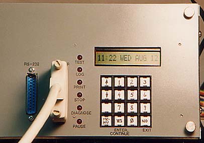
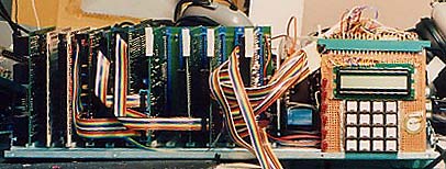
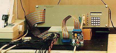
So is there another way? Well, yes, but software sure beats the hardware possibilities. My first computer, shown here, had a separate, non-multiplexed hex keypad that I debounced in hardware, and an 8-digit 7-segment display (before I knew about the LCD modules or how to do LED multiplexing) that had an 8-bit serial-in, parallel-out shift register for each digit and a current-limiting resistor for each of the 64 segments, with an impressive pile of thin wires. It was an awful lot of construction work for what I got out of it. I wrote the software for what segments to light for each character, something else you don't have to do with the intelligent character LCD modules. Making some of the characters in 7-segment required getting pretty creative. An "M" was an up-side-down "U", a "W" was an up-side-down "A", etc., and many specials were ridiculous combinations you had to look up until you had them memorized.

Quote:
I am wondering if I should get started first with PICs. There seem to be a lot more projects on those. They seem to be a little easier to implement too. I could learn a lot of the basics of I/O etc. then move back to my nostalgic dream project of building a 6502 based computer.

I've used them a lot. What they have going for them is that the whole thing is on one IC and there are lots of variations in stock at lots of distributors. You still have to connect your keypad and display and other I/O, and the sad part about the PICs is their decrepit microprocessor whose assembly language is much harder to program solutions in than the 6502 is. Hardwarewise the PIC is the quicker way to get going, but then in software, even doing something as simple as add-with-carry and subtract-with-borrow is pain. There's no direct access to the stack. The RAM and ROM memory banking is a big source of bugs. Table indexing becomes a ridiculous jerry-rig which if not done correctly won't just give you a wrong result but will even crash. Actually I could give you a ton of these, but it's better if I not get started because it gets me to wound up. It's just that so many things that are relatively efficient on the 6502 take a really mickey-mouse process to accomplish on the PIC, if indeed the PIC can do it at all. Over the years I have developed a lot of macros for use in the PIC assembler to try to hide some of the ugly details that shouldn't have to be so ugly.

Quote:
Once I move on to my 6501 project, it would be nice to find a use for these 6502s. I have a bunch of them. But if you think it would be easier for me to use the 65C02 then maybe I will pick up a couple of those.

I have over a hundred 6512's I bought for pennies on the dollar many years ago for something I had in mind and then I never used them, and now never will. I should probably eBay them if they're even worth the shipping to someone. They're a 6502 that requires the clock source to provide two non-overlapping signals.

I'll tell you another secret-- After you get your feet wet with the 6502, you might want to move to the 65816, as you'll find it is actually easier to program, even though initially it looks more daunting.

Quote:
What about the 6522s that I have? or is there also a CMOS version of those?

Yes, and there are hardware advantages to them, but the difference is not as pronounced as the NMOS-CMOS difference is in the processor. The current-production WDC 65c22's have a far greater drive capability than the NMOS ones, and in input mode the pins offer a CMOS load instead of an LSTTL load. Sometimes that's important for not loading a line. Unfortunately the only bug the NMOS 6522 had is still not corrected in the CMOS versions from any of the manufacturers. It has to do with inputting serial data to its shift register with an external clock source. There's a way around the problem, but it would be nice if they would just fix it.


Top
 Profile  
Reply with quote  
 Post subject:
PostPosted: Tue Nov 17, 2009 7:14 pm 
Offline

Joined: Mon Sep 28, 2009 3:48 am
Posts: 17
Do you have one of these left over from your Atari days?

http://cgi.ebay.com/ATARI-CX85-NUMERIC-KEYPAD-BOARD-EXCELLENT-CONDITION_W0QQitemZ300338033185QQcmdZViewItem?rvr_id=&itemid=300338033185

Maybe just me but I would go for either something retro like CX85 or an ugly hack. The CX85 is well documented and IIRC all info and power is from a single 9 pin joystick port. I think they had to use the 4 bits of the 6520 on the port for outputs and the pot and trigger inputs to make it work. Lots of info available anyway.

For ugly you could always use the keypad from a remote control. The cheapies are just a matrix on a printed circuit board with carbon painted conductive buttons to make the switch closure. You would have to cut off the existing keyboard controller chip but it kind of fits with your junk yard dog scheme of using what you have vs. modern high performance parts.

My first computer was an 1802 with only a 32 byte PROM. That was enough to read the hex keyboard and have commands for changing the program counter, load memory, read memory, single step, and run. You don't really need a sophisticated OS to do something. I think you would have trouble buying that weak of parts now but the point is even if you use a 16k EPROM you don't have to fill it. Ditto for the RAM, anything beyond a couple of hundred bytes is gravy but you will have a tough time finding small ones.

Rick


Top
 Profile  
Reply with quote  
 Post subject:
PostPosted: Wed Nov 18, 2009 2:26 am 
Offline

Joined: Mon Mar 02, 2009 7:27 pm
Posts: 3258
Location: NC, USA
1802, jeez. I remember looking at the spec sheets of that CPU in my dad's basement. He had a few, along with boxes of MOS 6502's. The one's that failed testing. Looked interesting, but I think the address bus was multiplexed or something. Flashback, sorry... Very interesting processor worth investigating?

_________________
65Org16:https://github.com/ElEctric-EyE/verilog-6502


Last edited by ElEctric_EyE on Wed Nov 18, 2009 2:54 am, edited 1 time in total.

Top
 Profile  
Reply with quote  
 Post subject:
PostPosted: Wed Nov 18, 2009 3:47 am 
Offline

Joined: Mon Sep 28, 2009 3:48 am
Posts: 17
ElEctric_EyE wrote:
1802, jeez. I remember looking .at the spec sheets of that CPU in my dad's basement. He had a few, along with boxes of MOS 6502's. The one's that failed testing. Looked interesting, but I think the address bus was multiplexed or something. Flashback, sorry...


It was one of those 'you had to be there' in the late 70s to appreciate it. I think a construction article in Radio Electronics magazine and that kicked it off with a couple of outfits selling kits.

Yes, you had to latch the upper 8 bits of address since they were multiplexed. Thing is back then mine only had 256 bytes of RAM and the 32 byte PROM so you didn't have to do a lot of latching. :lol:

Small bit of trivia but Steve Wozniak's sweet 16 processor emulator was made to emulate the 1802. You have sixteen 16 bit registers that can be used for everything from scratch pads to the program counter. You could do stuff like load your subroutine address into a scratch pad register then change that register to the program counter to execute it like a subroutine w/o stack use. Return was just restore the original register I think or maybe dec or inc it a byte or two. All kinds of instructions that reminded you a coffee grinder. You could store via and auto increment a pointer register with a single instruction. I think Pittman<?> put tiny basic in ~1800 bytes. For the 6502 it was something like 2,200 bytes which really hurt at the time: Needed 2 EPROMs.

It is a storied processor in that it was used for a lot of NASA deep space probes. Been to Mars, Jupiter, Saturn, and beyond. Never got good market penatration for consumers and IIRC their 32 bit version was underwhelming.

My son took mine to work and never bothered to get it back to me when he left. I occasionally see them for sale on eBay for ~$1500 but I don't think there are any buyers at that price.

Just as well, technological dead end.

Rick


Top
 Profile  
Reply with quote  
 Post subject:
PostPosted: Wed Nov 18, 2009 4:44 am 
Offline
User avatar

Joined: Fri Aug 30, 2002 1:09 am
Posts: 8462
Location: Southern California
This is getting pretty O.T., but a friend of mine did his EE senior project in '82 with an 1802 partly because all the onboard registers meant he didn't need any RAM (plus, the old standby excuse, he was familiar with it because of his RCA COSMAC Elf computer). I believe the 1802 went into a lot of space projects because it was one of the first CMOS processors and was even rad-hard. Performancewise it was a dog though. I can't believe how many clocks it took to carry out an instruction. Very...very...slow!


Top
 Profile  
Reply with quote  
 Post subject:
PostPosted: Wed Nov 18, 2009 1:35 pm 
Offline
User avatar

Joined: Mon Dec 08, 2008 6:32 pm
Posts: 143
Location: Brighton, England
Spinnaker asked:
Quote:
Is there a simple circuit that I can build that will let me test these 6502s?


Not if you want a full functional test, but if you just want a working / failed test, try the following.

Connect the CPU to a 5V supply. Connect IRQ, NMI and RDY directly to +5V. Connect RESET to +5V through a 4.7k resistor. Connect D7, D5, D3 and D0 to +5V. Connect D6, D4, D2 and D1 to 0V

Feed a clock signal into the phase-0 input. If the CPU is working, you should get square waves on the address pins, with each address pin having a frequency half that of the previous one (A0 has highest frequency).

The CPU might not start on power-up, if it doesn't, briefly short the RESET pin to ground.

This test makes the CPU continually execute LDA #A9. Whilst it doesn't do a full functional test, it does confirm that the CPU is basicly working and only requires a resistor and a clock oscillator.

_________________
Shift to the left,
Shift to the right,
Mask in, Mask Out,
BYTE! BYTE! BYTE!


Top
 Profile  
Reply with quote  
 Post subject:
PostPosted: Fri Nov 20, 2009 11:42 pm 
Offline
User avatar

Joined: Fri Dec 12, 2008 10:40 pm
Posts: 1003
Location: Canada
Spinnaker:

Oh, please don't go the PIC route! They are soul-less products of modern engineering. There is no fun or enjoyment to be had using them. They are too easy and work too well.

Stick with the NMOS 6502. Seriously. I get that this is a hobby, right? Then there will be little fun is something like a PIC. Let that come later once you think of projects that may need multiple controllers or once you’ve had enough fun.

On the I/O, did you consider an ACIA? A KIM work-alike could easily be made using serial I/O. If you are dead keen on the HEX keypad, you might want to look into a 74C922. It will do all the decoding and de-bouncing for you in a single IC.

_________________
Bill


Top
 Profile  
Reply with quote  
Display posts from previous:  Sort by  
Post new topic Reply to topic  [ 34 posts ]  Go to page 1, 2, 3  Next

All times are UTC


Who is online

Users browsing this forum: No registered users and 4 guests


You cannot post new topics in this forum
You cannot reply to topics in this forum
You cannot edit your posts in this forum
You cannot delete your posts in this forum
You cannot post attachments in this forum

Search for:
Jump to: